Page 3960 of 4462

PS-12
STEERING COLUMN
Revision: 2006 December 2006 FX35/FX45
STEERING COLUMNPFP:48810
Removal and InstallationNGS000BY
COMPONENTS
CAUTION:
�Care must be taken not to give axial impact to steering column assembly during removal and
installation.
�Care must be taken not to move steering gear during removal of steering column assembly.
REMOVAL
1. Set vehicle to the straight ahead-direction.
2. Remove driver air bag module from steering wheel. Refer to SRS-38, "
DRIVER AIR BAG MODULE" .
3. Disconnect steering switch connector, remove steering wheel lock nut, then remove steering wheel. Refer to SRS-40, "
SPIRAL CABLE" .
4. Remove steering column cover. Refer to IP-10, "
INSTRUMENT PANEL ASSEMBLY" .
5. Remove combination switch & spiral cable from steering column assembly. Refer to SRS-40, "
SPIRAL
CABLE" .
6. Remove instrument lower panel (driver side). Refer to IP-10, "
INSTRUMENT PANEL ASSEMBLY" .
7. Remove combination meter. Refer to IP-10, "
INSTRUMENT PANEL ASSEMBLY" .
1. Steering wheel 2. Combination switch & spiral cable 3. Steering column assembly
4. Collar 5. Hole cover seal 6. Clamp
7. Hole cover 8. Lower shaft 9. Lower joint
Refer to GI-11, "
Components" , for the symbols in the figure.
SGIA1612E
Page 3962 of 4462

PS-14
STEERING COLUMN
Revision: 2006 December 2006 FX35/FX45
INSPECTION AFTER REMOVAL
�Check if there is something wrong with jacket tube of steering column assembly and collar etc. And then if
they are damaged, replace with new one.
�If vehicle has a collision light shocked, check column length “L”
as shown in the figure. Then if it is out of the specified value,
replace with new one.
�Check the turning torque of steering column with preload gauge
(SST). If it is out of the specified value, repair it or replace with
new one.
INSTALLATION
�Refer to PS-12, "COMPONENTS" for tightening torque. Install in the reverse order of removal.
NOTE:
Refer to component parts location and do not reuse non-reusable parts.
�After removing/installing or replacing steering components, check wheel alignment. Refer to FSU-6,
"Wheel Alignment Inspection" .
�After adjusting wheel alignment, adjust neutral position of steering angle sensor. Refer to BRC-6, "Adjust-
ment of Steering Angle Sensor Neutral Position" .
INSPECTION AFTER INSTALLATION
�Check tilt and telescopic mechanism operating range “L1 ”, “L2 ”
as shown in the figure.
�Check if steering wheel operation can turn to the end of the left
and right smoothly. Steering column length “L”: 572 mm (22.52 in)
Turning torque : 0 − 0.2 N·m (0 − 0.021 kg-m, 0 − 1 in-lb)
SGIA0556E
Tilt operating range “L1 ” : 28 - 32 mm (1.1 - 1.26 in)
Telescopic operating range
“L
2 ” : 18 - 22 mm (0.71 - 0.87 in)
SGIA1431E
Page 3965 of 4462

POWER STEERING GEAR AND LINKAGE PS-17
C
D E
F
H I
J
K L
M A
B
PS
Revision: 2006 December 2006 FX35/FX45
POWER STEERING GEAR AND LINKAGEPFP:49001
Removal and InstallationNGS000C3
CAUTION:
Spiral cable may snap due to steering operation if steering column is separated from steering gear
assembly. Therefore fix steering wheel with a string to avoid turns.
REMOVAL
1. Set wheels in the straight-ahead position.
2. Remove tires from vehicle with power tool.
3. Remove undercover with power tool.
4. Confirm slit of lower joint fits with the projection on rear cover cap, furthermore marking position on steering gear assembly
nearly fits with the projection on rear cover cap.
5. Remove cotter pin at steering outer socket, then loosen mount- ing nut.
6. Use a ball joint remover (SST) to remove steering outer socket from steering knuckle. Be careful not to damage ball joint boot.
CAUTION:
Tighten temporarily mounting nut to prevent damage to
threads and to prevent ball joint remover (SST) from com-
ing off.
1. Cotter pin 2. Steering gear assembly 3. Washer
4. Clip
SGIA1432E
SGIA0539E
SDIA1434E
Page 3966 of 4462
 from steering gear assembly, then drain fluid from pipings")
PS-18
POWER STEERING GEAR AND LINKAGE
Revision: 2006 December 2006 FX35/FX45
7. Remove oil pipings (high pressure side and low pressure side) from steering gear assembly, then drain fluid from pipings.
8. Remove mounting bolt of steering hydraulic piping bracket from steering gear assembly.
9. Remove mounting bolt (lower side) of lower joint.
10. Remove mounting bolts of steering gear assembly with power tool, and then remove steering gear assembly from vehicle.
INSTALLATION
�Refer to PS-17, "Removal and Installation" for tightening torque. Install in the reverse order of removal.
NOTE:
Refer to component parts location and do not reuse non-reusable parts.
�After removing/installing or replacing steering components, check wheel alignment. Refer to FSU-6,
"Wheel Alignment Inspection" .
�After adjusting wheel alignment, adjust neutral position of steering angle sensor. Refer to BRC-6, "Adjust-
ment of Steering Angle Sensor Neutral Position" .
SGIA0541E
SGIA0545E
SGIA0542E
SGIA0546E
Page 3967 of 4462
POWER STEERING GEAR AND LINKAGE PS-19
C
D E
F
H I
J
K L
M A
B
PS
Revision: 2006 December 2006 FX35/FX45
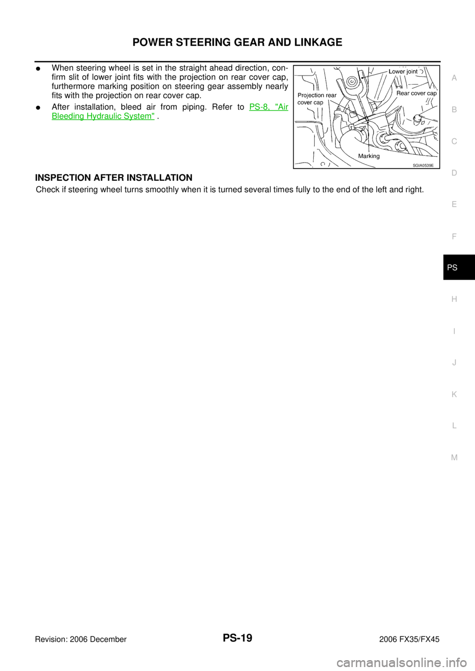
�When steering wheel is set in the straight ahead direction, con-
firm slit of lower joint fits with the projection on rear cover cap,
furthermore marking position on steering gear assembly nearly
fits with the projection on rear cover cap.
�After installation, bleed air from piping. Refer to PS-8, "Air
Bleeding Hydraulic System" .
INSPECTION AFTER INSTALLATION
Check if steering wheel turns smoothly when it is turned several times fully to the end of the left and right.
SGIA0539E
Page 3992 of 4462

Revision: 2006 December 2006 FX35/FX45
SERVICE DATA AND SPECIFICATIONS (SDS)PFP:00030
Steering WheelNGS000CE
Steering AngleNGS000CF
Steering ColumnNGS000CG")
PS-44
SERVICE DATA AND SPECIFICATIONS (SDS)
Revision: 2006 December 2006 FX35/FX45
SERVICE DATA AND SPECIFICATIONS (SDS)PFP:00030
Steering WheelNGS000CE
Steering AngleNGS000CF
Steering ColumnNGS000CG
Steering Outer Socket and Inner SocketNGS000CH
End play of the axle direction for steering wheel 0 mm (0 in)
Steering wheel play on the outer circumference 0 − 35 mm (0 − 1.38 in)
Inner wheel
Degree minute (Decimal degree) Minimum 32
°00 ′ (32.0 °)
Nominal 35 °00 ′ (35.0 °)
Maximum 36 °00 ′ (36.0 °)
Outer wheel
Degree minute (Decimal degree) Nominal 30
°00 ′ (30.0 °)
Steering column length “ L1 ” 572 mm (22.52 in)
SGIA0556E
Steering gear type PR26AM
Tie-rod ball joint outer socket Swinging torque 0.3
− 2.9 N·m (0.03 − 0.29 kg-m, 3 − 25 in-lb)
Measurement on spring balance
�Measuring point: cotter pin hole of stud 4.84
− 46.7 N (0.5 − 4.8 kg, 1.0 − 10 lb)
Rotating torque 0.3 − 2.9 N·m (0.03 − 0.29 kg-m, 3 − 25 in-lb)
Axial end play 0.5 mm (0.02 in) or less
Tie-rod ball joint inner socket Swinging torque 1.0
− 7.8 N·m (0.11 − 0.79 kg-m, 9 − 69 in-lb)
Measurement on spring balance
�Measuring point: L mark see below,
L=83.2 mm (3.28 in). 12.1
− 93.7 N (1.2 − 9.6 kg, 3.0 − 21 lb)
Axial end play 0.2 mm (0.01 in) or less
SGIA0358E
Page 3998 of 4462
 TROUBLESHOOTING
Revision: 2006 December 2006 FX35/FX45
NOISE, VIBRATION AND HARSHNESS (NVH) TROUBLESHOOTINGPFP:00003
NVH Troubleshooting ChartNDS000CG
Use ch")
RAX-4
NOISE, VIBRATION AND HARSHNESS (NVH) TROUBLESHOOTING
Revision: 2006 December 2006 FX35/FX45
NOISE, VIBRATION AND HARSHNESS (NVH) TROUBLESHOOTINGPFP:00003
NVH Troubleshooting ChartNDS000CG
Use chart below to help you find the cause of the symptom. If necessary, repair or replace these parts.
× : Applicable Reference page
—
RAX-9—
RAX-5—
NVH in PR section
NVH in RFD section
NVH in RAX and RSU section
Refer to REAR AXLE in this chart. NVH in WT section
NVH in WT section
Refer to DRIVE SHAFT in this chart. NVH in BR section
NVH in PS section
Possible cause and SUSPECTED PARTS
Excessive joint angle
Joint sliding resistance
Imbalance
Improper installation, looseness
Parts interference
PROPELLER SHAFT
DIFFERENTIAL
REAR AXLE AND REAR SUSPENSION
REAR AXLE
TIRES
ROAD WHEEL
DRIVE SHAFT
BRAKES
STEERING
Symptom DRIVE
SHAFT Noise
×× ×××××× ××
Shake ×× ×××××××
REAR
AXLE Noise
×× ××× ×××××
Shake ×××××××××
Vibration ×××××××
Shimmy ×× ×××××
Judder × × ×× ××
Poor quality ride or handling ×× × ××
Page 4000 of 4462

RAX-6
REAR WHEEL HUB AND KNUCKLE
Revision: 2006 December 2006 FX35/FX45
9. Remove parking brake cable and parking brake shoe from back plate. Refer to PB-6, "PARKING BRAKE
SHOE" and PB-4, "PARKING BRAKE CONTROL" .
10. Remove fixing nuts of anchor block with power tool, then remove anchor block and back plate from axle.
11. Loosen fixing bolts and nuts of front lower link, radius rod, and rear lower link in side of suspension mem- ber.
12. Set jack under rear lower link. Then remove fixing bolt in front lower link side of shock absorber with power tool.
13. Remove bolt and nut in axle side of rear lower link with power tool. Then remove coil spring. Refer to RSU-15, "
REAR LOWER LINK & COIL SPRING" .
14. Remove fixing bolts and nuts in axle side of front lower link, radius rod with power tool.
15. Remove suspension arm and cotter pin at axle, then loosen mounting nut.
16. Use a ball joint remover (suitable tool) to remove suspension arm from axle. Be careful not to damage ball joint boot.
CAUTION:
Tighten temporarily mounting nut to prevent damage to threads and to prevent ball joint remover
(suitable tool) from coming off.
17. Remove axle from vehicle.
INSPECTION AFTER REMOVAL
Check for deformity, cracks and damage on each parts, replace if necessary.
Ball Joint Inspection
Check for boot breakage, axial looseness, and torque of suspension arm ball joint. Refer to RSU-11,
"INSPECTION AFTER REMOVAL" .
INSTALLATION
�Refer to RAX-5, "Removal and Installation" for tightening torque. Install in the reverse order of removal.
NOTE:
Refer to component parts location and do not reuse non-reusable parts.
�Perform final tightening of installation position of suspension links (rubber bushing) under unladen condi-
tions with tires on level ground, Check wheel alignment. Refer to RSU-5, "
Wheel Alignment Inspection" .
�After adjusting wheel alignment, adjust neutral position of steering angle sensor. Refer to BRC-6, "Adjust-
ment of Steering Angle Sensor Neutral Position" .