Page 3101 of 4462
![INFINITI FX35 2006 Service Manual FRONT DRIVE SHAFT FAX-13
[AWD]
C E F
G H
I
J
K L
M A
B
FA X
Revision: 2006 December 2006 FX35/FX45
NOTE:
Refer to component parts location and do not reuse non-reusable parts.
�Check the f](/manual-img/42/57019/w960_57019-3100.png "INFINITI FX35 2006 Service Manual FRONT DRIVE SHAFT FAX-13
[AWD]
C E F
G H
I
J
K L
M A
B
FA X
Revision: 2006 December 2006 FX35/FX45
NOTE:
Refer to component parts location and do not reuse non-reusable parts.
�Check the f")
FRONT DRIVE SHAFT FAX-13
[AWD]
C E F
G H
I
J
K L
M A
B
FA X
Revision: 2006 December 2006 FX35/FX45
NOTE:
Refer to component parts location and do not reuse non-reusable parts.
�Check the following item after service.
–Installation condition of wheel sensor harness
Removal and Installation (Right Side)NDS000C7
COMPONENTS
REMOVAL
1. Remove tires from vehicle with power tool.
2. Remove undercover with power tool.
3. Remove cotter pin. Then remove lock nut from drive shaft with power tool.
4. Remove wheel sensor harness from strut assembly. Refer to BRC-55, "
WHEEL SENSORS" .
CAUTION:
Do not pull on wheel sensor harness.
5. Remove brake hose lock prate. Then remove brake hose from strut assembly. Refer to BR-11, "
BRAKE
TUBE AND HOSE" .
6. Remove fixing bolts and nuts between strut assembly and steering knuckle with power tool.
7. Using a puller (suitable tool), remove drive shaft from steering knuckle.
CAUTION:
When removing drive shaft, do not apply an excessive
angle to drive shaft joint. Also be careful not to excessively
extend slide joint.
8. Pry off drive shaft from front final drive assembly side as shown in the figure.
INSPECTION AFTER REMOVAL
�Move joint up/down, left/right, and in the axial direction. Check for any rough movement or significant
looseness.
1. Cotter pin 2. Washer 3. Drive shaft
Refer to GI-11, "
Components" , for the symbols in the figure.
PDIA1219E
SDIA0972J
SDIA1489E
Page 3120 of 4462
 TROUBLESHOOTING
Revision: 2006 December 2006 FX35/FX45
NOISE, VIBRATION AND HARSHNESS (NVH) TROUBLESHOOTINGPFP:00003
NVH Troubleshooting ChartNDS000B6
Use th")
FFD-6
NOISE, VIBRATION AND HARSHNESS (NVH) TROUBLESHOOTING
Revision: 2006 December 2006 FX35/FX45
NOISE, VIBRATION AND HARSHNESS (NVH) TROUBLESHOOTINGPFP:00003
NVH Troubleshooting ChartNDS000B6
Use the chart below to help you find the cause of the symptom. If necessary, repair or replace these parts.
× : Applicable Reference page
Refer to
FFD-28, "
INSPECTION AFTER DISASSEMBLY
" .
Refer to FFD-21, "
Tooth Contact
" .
Refer to FFD-28, "
INSPECTION AFTER DISASSEMBLY
" .
Refer to FFD-23, "
Backlash
" .
Refer to FFD-23, "
Companion Flange Runout
" .
Refer to FFD-8, "
Checking Differential Gear Oil
" .
NVH in PR section.
NVH in FAX, RAX, FSU and RSU sections.
NVH in WT section.
NVH in WT section.
NVH in FAX and RAX section.
NVH in BR section.
NVH in PS section.
Possible cause and SUSPECTED PARTS
Gear tooth rough
Gear contact improper
Tooth surfaces worn
Backlash incorrect
Companion flange excessive runout
Gear oil improper
PROPELLER SHAFT
AXLE AND SUSPENSION
TIRES
ROAD WHEEL
DRIVE SHAFT
BRAKES
STEERING
Symptom Noise ×××××××××××××
Page 3165 of 4462

FUEL TANK FL-11
C
D E
F
G H
I
J
K L
M A
FL
Revision: 2006 December 2006 FX35/FX45
9. Disconnect fuel filler hose, vent hose and EVAP hoses at fuel tank side.
10. Support the lower part of fuel tank with transmission jack. CAUTION:
Support the position that fuel tank mounting bands do not
engage.
11. Remove fuel tank mounting bands.
12. Supporting with hands, descend transmission jack carefully, and remove fuel tank. CAUTION:
�Make sure that all connection points have been disconnected.
�Confirm there is no interference with vehicle.
13. Remove fuel filler tube protector and fuel filler tube, if necessary.
INSTALLATION
Note the following, and install in the reverse order of removal.
�Surely clamp fuel hoses and insert hose to the length below.
�Be sure hose clamp is not placed on swelled area of fuel tube.
�Tighten fuel hose clamp so that the distance between its lugs becomes to the following.
�To connect quick connector, refer to FL-7, "Quick Connector" .
INSPECTION AFTER INSTALLATION
Use the following procedure to check for fuel leaks.
1. Turn ignition switch “ON” (with engine stopped), and check connections for leakage by applying fuel pres- sure to fuel piping.
2. Start engine and rev it up and make sure there are no fuel leaks at the fuel system tube and hose connec- tions.
�After removing/installing rear suspension assembly, make sure to adjust wheel alignment and then, adjust
neutral position of steering angle sensor. Refer to RSU-5, "
Wheel Alignment Inspection" and BRC-6,
"Adjustment of Steering Angle Sensor Neutral Position" .
PBIC1581E
PBIC0878E
Fuel filler hose : 35 mm (1.38 in)
The other hoses : 25 mm (0.98 in)
Fuel tank side : 8 - 12 mm (0.31 - 0.47 in)
Fuel filler tube side : 5.7 - 9.7 mm (0.224 - 0.382 in)
Page 3169 of 4462
NES000FL
The actual shapes of Kent-Moore tools may diff")
PREPARATION FSU-3
C
D
F
G H
I
J
K L
M A
B
FSU
Revision: 2006 December 2006 FX35/FX45
PREPARATIONPFP:00002
Special Service Tools (SST)NES000FL
The actual shapes of Kent-Moore tools may differ from those of special service tools illustrated here.
Tool number
(Kent-Moore No.)
Tool name Description
KV991040S0
( — )
CCK gauge attachment
1. Plate
2. Guide bolts
3. Nuts
4. Springs
5. Center plate
6. KV9910 4020 Adapter A
a: 72 mm (2.83 in) dia.
7. KV9910 4030 Adapter B
b: 65 mm (2.56 in) dia.
8. KV9910 4040 Adapter C
c: 57 mm (2.24 in) dia.
9. KV9910 4050 Adapter D
d: 53.4 mm (2.102 in) dia. Measuring wheel alignment
HT72520000
(J25730-A)
Ball joint remover
a: 33 mm (1.30 in)
b: 50 mm (1.97 in)
r: 11.5 mm (0.453 in)
�Removing steering outer socket
�Removing transverse link
ST35652000
( — )
Strut attachment Disassembling and assembling strut
ST3127 S000
(See J −25742-1)
Preload gauge
1. GG91030000
Torque wrench (J −25765)
2. HT62940000 ( — )
Socket adapter (1/2 ″)
3. HT62900000 ( — )
Socket adapter (3/8 ″) Measuring rotating torque of ball joint
S-NT498
NT546
ZZA0807D
NT124
Page 3170 of 4462
FSU-4
PREPARATION
Revision: 2006 December 2006 FX35/FX45
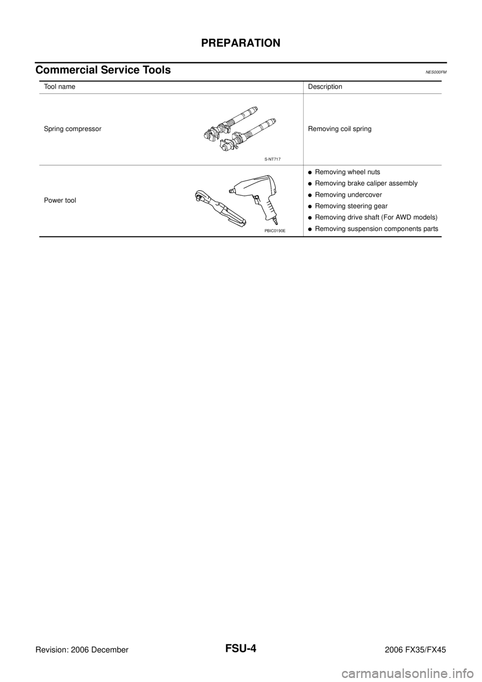
Commercial Service ToolsNES000FM
Tool name Description
Spring compressor Removing coil spring
Power tool
�Removing wheel nuts
�Removing brake caliper assembly
�Removing undercover
�Removing steering gear
�Removing drive shaft (For AWD models)
�Removing suspension components parts
S-NT717
PBIC0190E
Page 3171 of 4462
 TROUBLESHOOTING FSU-5
C
D
F
G H
I
J
K L
M A
B
FSU
Revision: 2006 December 2006 FX35/FX45
NOISE, VIBRATION AND HARSHNESS (NVH) TROUBLESHOOTINGPFP:00003")
NOISE, VIBRATION AND HARSHNESS (NVH) TROUBLESHOOTING FSU-5
C
D
F
G H
I
J
K L
M A
B
FSU
Revision: 2006 December 2006 FX35/FX45
NOISE, VIBRATION AND HARSHNESS (NVH) TROUBLESHOOTINGPFP:00003
NVH Troubleshooting ChartNES000FN
Use chart below to help you find the cause of the symptom. If necessary, repair or replace these parts.
× : Applicable Reference page
FSU-8FSU-12
—
—
—
FSU-8FSU-6FSU-16
NVH in PR section
NVH in RFD section
NVH in FAX and FSU section
NVH in WT section
NVH in WT section
NVH in FAX section NVH in BR section NVH in PS section
Possible cause and SUSPECTED PARTS
Improper installation, looseness
Strut deformation, damage or deflection
Bushing or mounting deterioration
Parts interference
Spring fatigue
Suspension looseness
Incorrect wheel alignment
Stabilizer bar fatigue
PROPELLER SHAFT (For AWD models)
DIFFERENTIAL (For AWD models)
FRONT AXLE AND FRONT SUSPENSION
TIRES
ROAD WHEEL
DRIVE SHAFT (For AWD models)
BRAKES
STEERING
Symptom FRONT SUSPENSION Noise
××××× × ××× ×××××
Shake ×××× × × × ×××××
Vibration ××××× × ×× × ×
Shimmy ×××× × ××× ××
Judder ××× ××× ××
Poor quality ride or han-
dling ××××× ×× ×××
Page 3172 of 4462

FSU-6
FRONT SUSPENSION ASSEMBLY
Revision: 2006 December 2006 FX35/FX45
FRONT SUSPENSION ASSEMBLYPFP:54010
On-Vehicle Inspection and ServiceNES000I3
Make sure the mounting conditions (looseness, back lash) of each component and component conditions
(wear, damage) are normal.
INSPECTION LOWER BALL JOINT END PLAY
1. Set front wheels in a straight-ahead position. Do not depress brake pedal.
2. Place an iron bar or similar tool between transverse link and steering knuckle.
3. Measure axial end play by prying it up and down.
CAUTION:
Be careful not to damage ball joint boot.
STRUT INSPECTION
�Check strut for oil leakage, damage and replace if there are. Refer to FSU-11, "COIL SPRING AND
STRUT" .
Wheel Alignment InspectionNES000I4
DESCRIPTION
�Measure wheel alignment under unladen conditions.
NOTE:
Unladen conditions mean that fuel, engine coolant, and lubricant are full. Spare tire, jack, hand tools and
mats are designated positions.
PRELIMINARY CHECK
�Check tires for improper air pressure and wear.
�Check road wheels for runout.
�Check wheel bearing axial end play.
�Check ball joint axial end play of compression rod, upper link, and steering knuckle
�Check shock absorber operation.
�Check each mounting part of axle and suspension for looseness and deformation.
�Check each link, rod and member for cracks, deformation and other damage.
�Check vehicle posture.
GENERAL INFORMATION AND RECOMMENDATIONS
�A four-wheel thrust alignment should be performed.
–This type of alignment is recommended for any NISSAN/INFINITI vehicle.
–The four-wheel “thrust” process helps ensure that the vehicle is properly aligned and the steering wheel is
centered.
–The alignment rack itself should be capable of accepting any NISSAN/INFINITI vehicle.
–The rack should be checked to ensure that it is level.
�Make sure the machine is properly calibrated.
–Your alignment equipment should be regularly calibrated in order to give correct information.
–Check with the manufacturer of your specific equipment for their recommended Service/Calibration
Schedule. Axial end play : 0 mm (0 in)
Page 3175 of 4462

FRONT SUSPENSION ASSEMBLY FSU-9
C
D
F
G H
I
J
K L
M A
B
FSU
Revision: 2006 December 2006 FX35/FX45
REMOVAL
1. Set an engine slinger to engine, then suspend engine.
2. Remove tire from vehicle with power tool.
3. Remove brake caliper with power tool. Hang it in a place where it will not interfere with work. Refer to BR-
19, "FRONT DISC BRAKE" .
4. Remove brake hose lock plate. Then remove brake hose from strut assembly.
5. Remove disc rotor.
6. Remove wheel sensor harness from strut assembly. CAUTION:
Do not pull on wheel sensor harness.
7. Remove undercover with power tool.
8. Remove front cross bar.
9. Remove steering hydraulic piping bracket from front suspension member. Refer to PS-39, "
HYDRAULIC LINE" .
10. Remove cotter pin at steering outer socket, then loosen mount- ing nut.
11. Use a ball joint remover (SST) to remove steering outer socket from steering knuckle. Be careful not to damage ball joint boot.
CAUTION:
Tighten temporarily mounting nut to prevent damage to
threads and to prevent ball joint remover (SST) from com-
ing off.
12. Remove mounting bolts of steering gear with power tool, then hang steering gear on vehicle. Refer to PS-17, "
POWER
STEERING GEAR AND LINKAGE" .
13. Remove front final drive side of drive shaft with power tool. (For AWD models) Refer to FAX-12, "
Removal and Installation (Left
Side)" , FA X - 1 3 , "Removal and Installation (Right Side)" .
14. Set jack under front suspension member.
15. Remove fixing bolts and nuts between strut assembly and steering knuckle with power tool.
1. Strut upper plate 2. Strut spacer 3. Mounting insulator
4. Mounting insulator bracket 5. Mounting bearing 6. Spring upper seat
7. Spring upper rubber seat 8. Coil spring 9. Spring lower rubber seat
10. Bound bumper 11. Strut 12. Steering knuckle
13. Front suspension member 14. Transverse link 15. Stabilizer bar
16. Stabilizer bushing 17. Stabilizer clamp 18. Stabilizer connecting rod
19. Front cross bar 20. Cotter pin
Refer to GI-11, "
Components" , for the symbols in the figure.
SEIA0328E
SEIA0329E
SDIA1434E