Page 3086 of 4462
EX-4
EXHAUST SYSTEM
Revision: 2006 December 2006 FX35/FX45
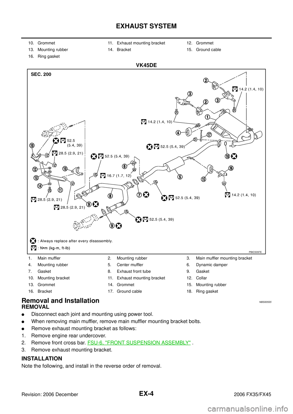
VK45DE
Removal and InstallationNBS005S5
REMOVAL
�Disconnect each joint and mounting using power tool.
�When removing main muffler, remove main muffler mounting bracket bolts.
�Remove exhaust mounting bracket as follows:
1. Remove engine rear undercover.
2. Remove front cross bar. FSU-6, "
FRONT SUSPENSION ASSEMBLY" .
3. Remove exhaust mounting bracket.
INSTALLATION
Note the following, and install in the reverse order of removal.
10. Grommet 11. Exhaust mounting bracket 12. Grommet
13. Mounting rubber 14. Bracket 15. Ground cable
16. Ring gasket
PBIC5097E
1. Main muffler 2. Mounting rubber 3. Main muffler mounting bracket
4. Mounting rubber 5. Center muffler 6. Dynamic damper
7. Gasket 8. Exhaust front tube 9. Gasket
10. Mounting bracket 11. Exhaust mounting bracket 12. Collar
13. Grommet 14. Grommet 15. Mounting rubber
16. Bracket 17. Ground cable 18. Ring gasket
Page 3087 of 4462

EXHAUST SYSTEM EX-5
C
D E
F
G H
I
J
K L
M A
EX
Revision: 2006 December 2006 FX35/FX45
�Tighten main muffler mounting bracket bolts in numerical order
as shown in the figure.
CAUTION:
�Always replace exhaust tube gaskets with new ones when reassembling.
�If heat insulator is badly deformed, repair or replace it. If deposits such as mud pile up on the heat
insulator, remove them.
�When installing heat insulator avoid large gaps or interference between heat insulator and each
exhaust pipe.
�Remove deposits from the sealing surface of each connection. Connect them securely to avoid
gases leakage.
�Temporarily tighten mounting nuts on the exhaust manifold side and mounting bolts on the vehi-
cle side. Check each part for unusual interference, and then tighten them to the specified torque.
�When installing each mounting rubber, avoid twisting or unusual extension in up/down and right/
left directions.
INSPECTION AFTER INSTALLATION
�Make sure clearance between tail tube and bumper is even.
�With engine running, check exhaust tube joints for gas leakage and unusual noises.
�Check to ensure that mounting brackets and mounting rubbers are installed properly and free from undue
stress. Improper installation could result in excessive noise and vibration.
PBIC1049E
Page 3088 of 4462
EX-6
EXHAUST SYSTEM
Revision: 2006 December 2006 FX35/FX45
Page 3155 of 4462

FL-1
FUEL SYSTEM
B ENGINE
CONTENTS
C
D E
F
G H
I
J
K L
M
SECTION FL
A
FL
Revision: 2006 December 2006 FX35/FX45
FUEL SYSTEM
PREPARATION ...................................................... ..... 2
Commercial Service Tools ................................... ..... 2
FUEL SYSTEM ...................................................... ..... 3
Checking Fuel Lines ............................................ ..... 3
General Precautions ........................................... ..... 3
FUEL LEVEL SENSOR UNIT, FUEL FILTER AND
FUEL PUMP ASSEMBLY ...................................... ..... 4
Components ........................................................ ..... 4
Removal and Installation ..................................... ..... 4
REMOVAL ........................................................ ..... 4
INSTALLATION ................................................ ..... 6
INSPECTION AFTER INSTALLATION ............ ..... 7 Components ........................................................
..... 8
Disassembly and Assembly ................................. ..... 8
DISASSEMBLY ................................................ ..... 8
ASSEMBLY ...................................................... ..... 9
FUEL TANK ........................................................... ... 10
Components ........................................................ ... 10
Removal and Installation ..................................... ... 10
REMOVAL ........................................................ ... 10
INSTALLATION ................................................ ... 11
INSPECTION AFTER INSTALLATION ............. ... 11
SERVICE DATA AND SPECIFICATIONS (SDS) ... ... 12
Standard and Limit ............................................... ... 12
FUEL TANK ...................................................... ... 12
Page 3157 of 4462

FUEL SYSTEM FL-3
C
D E
F
G H
I
J
K L
M A
FL
Revision: 2006 December 2006 FX35/FX45
FUEL SYSTEMPFP:17503
Checking Fuel LinesNBS004IG
Inspect fuel lines, fuel filler cap and fuel tank for improper attach-
ment, leaks, cracks, damage, loose connections, chafing or deterio-
ration.
If necessary, repair or replace damaged parts.
General PrecautionsNBS004IH
WARNING:
When replacing fuel line parts, be sure to observe the following.
�Put a “CAUTION: FLAMMABLE” sign in the workshop.
�Be sure to work in a well ventilated area and furnish workshop with a CO2 fire extinguisher.
�Do not smoke while servicing fuel system. Keep open flames and sparks away from the work area.
CAUTION:
�Use gasoline required by the regulations for octane number. Refer to GI-6, "Precautions for Fuel
(Unleaded Premium Gasoline Recommended)" .
�Before removing fuel line parts, carry out the following procedures:
–Put drained fuel in an explosion-proof container and put the lid on securely. Keep the container in
safe area.
–Release fuel pressure from the fuel lines. Refer to EC-86, "FUEL PRESSURE RELEASE" (VQ35DE)
or EC-746, "
FUEL PRESSURE RELEASE" (VK45DE).
–Disconnect negative battery terminal.
�Always replace O-ring and clamps with new ones.
�Do not kink or twist tubes when they are being installed.
�Do not tighten hose clamps excessively to avoid damaging hoses.
�After connecting fuel tube quick connectors, make sure
quick connectors are secure.
Ensure that connector and resin tube do not contact any
adjacent parts.
�After installing tubes, make sure there is no fuel leakage at
connections in the following steps.
–Apply fuel pressure to fuel lines with turning ignition switch
“ON” (with engine stopped). Then check for fuel leaks at
connections.
–Start engine and rev it up and check for fuel leaks at con-
nections.
�Use only a genuine NISSAN fuel filler cap as a replacement.
If an incorrect fuel filler cap is used, the “MIL” may come
on.
�For servicing “Evaporative Emission System” parts, refer to
EC-39, "
EVAPORATIVE EMISSION SYSTEM" (VQ35DE) or
EC-699, "
EVAPORATIVE EMISSION SYSTEM" (VK45DE).
�For servicing“On Board Refueling Vapor Recovery (ORVR)”
parts, refer to EC-46, "
ON BOARD REFUELING VAPOR
RECOVERY (ORVR)" (VQ35DE) or EC-706, "ON BOARD
REFUELING VAPOR RECOVERY (ORVR)" (VK45DE).
SMA803A
SBIA0504E
Page 3158 of 4462

FL-4
FUEL LEVEL SENSOR UNIT, FUEL FILTER AND FUEL PUMP ASSEMBLY
Revision: 2006 December 2006 FX35/FX45
FUEL LEVEL SENSOR UNIT, FUEL FILTER AND FUEL PUMP ASSEMBLYPFP:17042
ComponentsNBS004II
Removal and InstallationNBS005S2
REMOVAL
WARNING:
Read “General Precautions” when working on the fuel system. Refer to FL-3, "
General Precautions" .
1. Check fuel level on fuel gauge. If fuel gauge indicates more than the level as shown in the figure (full or almost full), drain fuel
from fuel tank until fuel gauge indicates level as shown in the fig-
ure or below.
NOTE:
Because fuel will be spilled when removing main and sub fuel
level sensor units for the top of the fuel is above the main and
sub fuel level sensor units installation surface.
�As a guide, fuel level becomes the position as shown in the
figure or below when approximately 20 (5-1/4 US gal, 4-3/8
Imp gal) of fuel are drained from fuel tank.
�In a case that fuel pump does not operate, perform the follow-
ing procedure.
a. Insert hose of less than 25 mm (0.98 in) in diameter into fuel filler tube through fuel filler opening to draw fuel from fuel filler tube.
b. Disconnect fuel filler hose from fuel filler tube. Refer to FL-10, "
FUEL TANK" .
c. Insert fuel tube into fuel tank through fuel filler hose to draw fuel from fuel tank.
2. Release the fuel pressure from the fuel lines. Refer to EC-86, "
FUEL PRESSURE RELEASE" (VQ35DE)
or EC-746, "
FUEL PRESSURE RELEASE" (VK45DE).
1. Retainer 2. Main fuel level sensor unit, fuel filter -
and fuel pump assembly 3. O-ring
4. Sub fuel level sensor unit
PBIC1585E
PBIC1575E
Page 3162 of 4462
, then check connections for leaks by apply")
FL-8
FUEL LEVEL SENSOR UNIT, FUEL FILTER AND FUEL PUMP ASSEMBLY
Revision: 2006 December 2006 FX35/FX45
1. Turn ignition switch “ON” (with engine stopped), then check connections for leaks by applying fuel pres- sure to fuel piping.
2. Start engine and let it idle and make sure there are no fuel leaks at the fuel system connections.
ComponentsNBS004IJ
Disassembly and AssemblyNBS005S3
CAUTION:
Sub fuel level sensor unit cannot be disassembled and should be replaced as a unit.
DISASSEMBLY
Remove fuel level sensor unit as follows.
1. Disconnect harness connector.
�Hold connector by fingers and pull it out, because there is no
stopper release tab.
2. Using suitable tool, pull up tabs points as shown in the figure (two points) to release the lock.
CAUTION:
Be careful not to damage it.
3. After fixing tabs are disengaged, slide fuel level sensor unit out in direction shown by the arrow.
CAUTION:
Do not disassemble fuel filter and fuel pump assembly.
1. Fuel level sensor unit 2. Fuel filter and fuel pump assembly
PBIC1081E
PBIC1078E
PBIC1654E
PBIC1080E
Page 3164 of 4462

FL-10
FUEL TANK
Revision: 2006 December 2006 FX35/FX45
FUEL TANKPFP:17202
ComponentsNBS004IK
Removal and InstallationNBS005S4
REMOVAL
WARNING:
Be sure to read “General Precautions” when working on the fuel system. Refer to FL-3, "
General Pre-
cautions" .
�Drain fuel from fuel tank if necessary. Refer to FL-4, "REMOVAL" .
�Perform work on level place.
1. Perform steps 2 to 7 of “REMOVAL” in “ FUEL LEVEL SENSOR UNIT, FUEL FILTER AND FUEL PUMP ASSEMBLY” on main and sub fuel level sensor units. Refer to FL-4, "
REMOVAL" .
2. Remove tunnel stay. Refer to RSU-5, "
REAR SUSPENSION ASSEMBLY" .
3. Remove exhaust front tube, center muffler and main muffler. Refer to EX-3, "
EXHAUST SYSTEM" .
4. Remove insulator.
5. Remove propeller shaft. Refer to PR-7, "
REAR PROPELLER SHAFT" .
6. Remove parking rear brake cables. Refer to PB-4, "
PARKING BRAKE CONTROL" .
7. Remove rear suspension assembly. Refer to RSU-5, "
REAR SUSPENSION ASSEMBLY" .
8. Remove fuel tank protector.
1. Grommet 2. Fuel filler cap 3. Clip
4. Fuel filler tube protector 5. Fuel tank mounting band 6. Fuel tank protector
7. Insulator 8. Fuel tank 9. Vent tube
10. Vent hose 11. EVAP hose 12. Vent hose
13. Fuel filler hose 14. Fuel filler tube
PBIC1580E