Page 3286 of 4462
GW-46
POWER WINDOW SYSTEM
Revision: 2006 December 2006 FX35/FX45
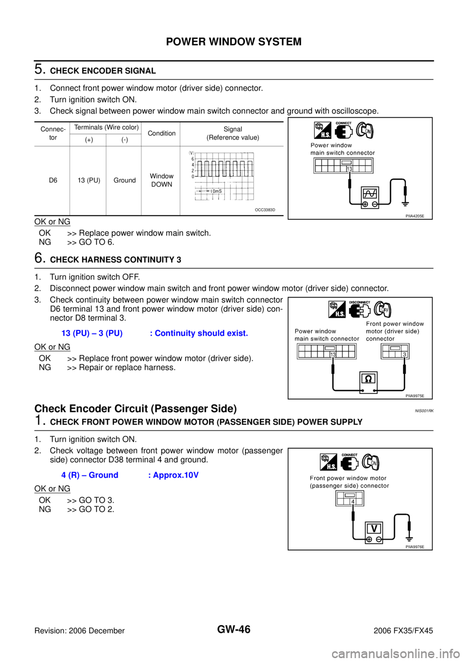
5. CHECK ENCODER SIGNAL
1. Connect front power window motor (driver side) connector.
2. Turn ignition switch ON.
3. Check signal between power window main switch connector and ground with oscilloscope.
OK or NG
OK >> Replace power window main switch.
NG >> GO TO 6.
6. CHECK HARNESS CONTINUITY 3
1. Turn ignition switch OFF.
2. Disconnect power window main switch and front power window motor (driver side) connector.
3. Check continuity between power window main switch connector D6 terminal 13 and front power window motor (driver side) con-
nector D8 terminal 3.
OK or NG
OK >> Replace front power window motor (driver side).
NG >> Repair or replace harness.
Check Encoder Circuit (Passenger Side)NIS001RK
1. CHECK FRONT POWER WINDOW MOTOR (PASSENGER SIDE) POWER SUPPLY
1. Turn ignition switch ON.
2. Check voltage between front power window motor (passenger side) connector D38 terminal 4 and ground.
OK or NG
OK >> GO TO 3.
NG >> GO TO 2.
Connec-
tor Terminals (Wire color)
Condition Signal
(Reference value)
(+) (-)
D6 13 (PU) Ground Window
DOWN
PIIA4205EOCC3383D
13 (PU) – 3 (PU) : Continuity should exist.
PIIA9975E
4 (R) – Ground : Approx.10V
PIIA9976E
Page 3287 of 4462
POWER WINDOW SYSTEM GW-47
C
D E
F
G H
J
K L
M A
B
GW
Revision: 2006 December 2006 FX35/FX45
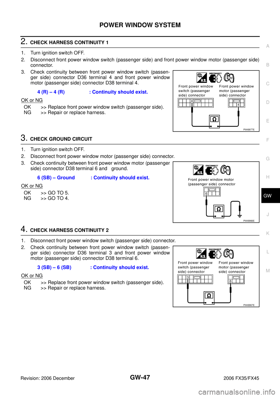
2. CHECK HARNESS CONTINUITY 1
1. Turn ignition switch OFF.
2. Disconnect front power window switch (passenger side) and front power window motor (passenger side) connector.
3. Check continuity between front power window switch (passen- ger side) connector D36 terminal 4 and front power window
motor (passenger side) connector D38 terminal 4.
OK or NG
OK >> Replace front power window switch (passenger side).
NG >> Repair or replace harness.
3. CHECK GROUND CIRCUIT
1. Turn ignition switch OFF.
2. Disconnect front power window motor (passenger side) connector.
3. Check continuity between front power window motor (passenger side) connector D38 terminal 6 and ground.
OK or NG
OK >> GO TO 5.
NG >> GO TO 4.
4. CHECK HARNESS CONTINUITY 2
1. Disconnect front power window switch (passenger side) connector.
2. Check continuity between front power window switch (passen- ger side) connector D36 terminal 3 and front power window
motor (passenger side) connector D38 terminal 6.
OK or NG
OK >> Replace front power window switch (passenger side).
NG >> Repair or replace harness. 4 (R) – 4 (R) : Continuity should exist.
PIIA9977E
6 (SB) – Ground : Continuity should exist.
PIIA9966E
3 (SB) – 6 (SB) : Continuity should exist.
PIIA9967E
Page 3288 of 4462
GW-48
POWER WINDOW SYSTEM
Revision: 2006 December 2006 FX35/FX45
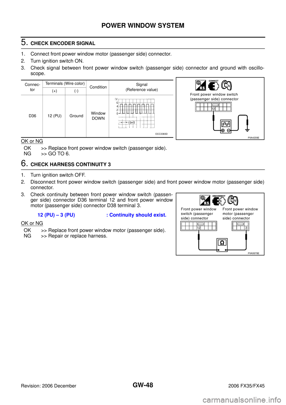
5. CHECK ENCODER SIGNAL
1. Connect front power window motor (passenger side) connector.
2. Turn ignition switch ON.
3. Check signal between front power window switch (passenger side) connector and ground with oscillo- scope.
OK or NG
OK >> Replace front power window switch (passenger side).
NG >> GO TO 6.
6. CHECK HARNESS CONTINUITY 3
1. Turn ignition switch OFF.
2. Disconnect front power window switch (passenger side) and front power window motor (passenger side) connector.
3. Check continuity between front power window switch (passen- ger side) connector D36 terminal 12 and front power window
motor (passenger side) connector D38 terminal 3.
OK or NG
OK >> Replace front power window motor (passenger side).
NG >> Repair or replace harness.
Connec-
tor Terminals (Wire color)
Condition Signal
(Reference value)
(+) (-)
D36 12 (PU) Ground Window
DOWN
PIIA4209EOCC3383D
12 (PU) – 3 (PU) : Continuity should exist.
PIIA9978E
Page 3289 of 4462
POWER WINDOW SYSTEM GW-49
C
D E
F
G H
J
K L
M A
B
GW
Revision: 2006 December 2006 FX35/FX45
Check Door Switch NIS001RM
1. CHECK DOOR SWITCH INPUT SIGNAL
With CONSULT-II
Check (“DOOR SW-DR” and “DOOR SW-AS”) in “DATA MONITOR” mode with CONSULT-II.
Without CONSULT-II
Check voltage between BCM connector M3, B14 terminals 12, 62 and ground.
OK or NG
OK >> Door switch is OK.
NG >> GO TO 2.
Monitor item Condition
DOOR SW-DR OPEN : ON
CLOSE : OFF
DOOR SW-AS OPEN : ON
CLOSE : OFF
PIIA2464E
Item Terminals (Wire color)
Door condition Voltage [V]
(Approx.)
(+) (–)
Passenger side
door switch 12 (P/B)
Ground OPEN 0
CLOSE Battery voltage
Driver side door
switch 62 (W) OPEN 0
CLOSE Battery voltage
PIIA6158E
Page 3290 of 4462
GW-50
POWER WINDOW SYSTEM
Revision: 2006 December 2006 FX35/FX45
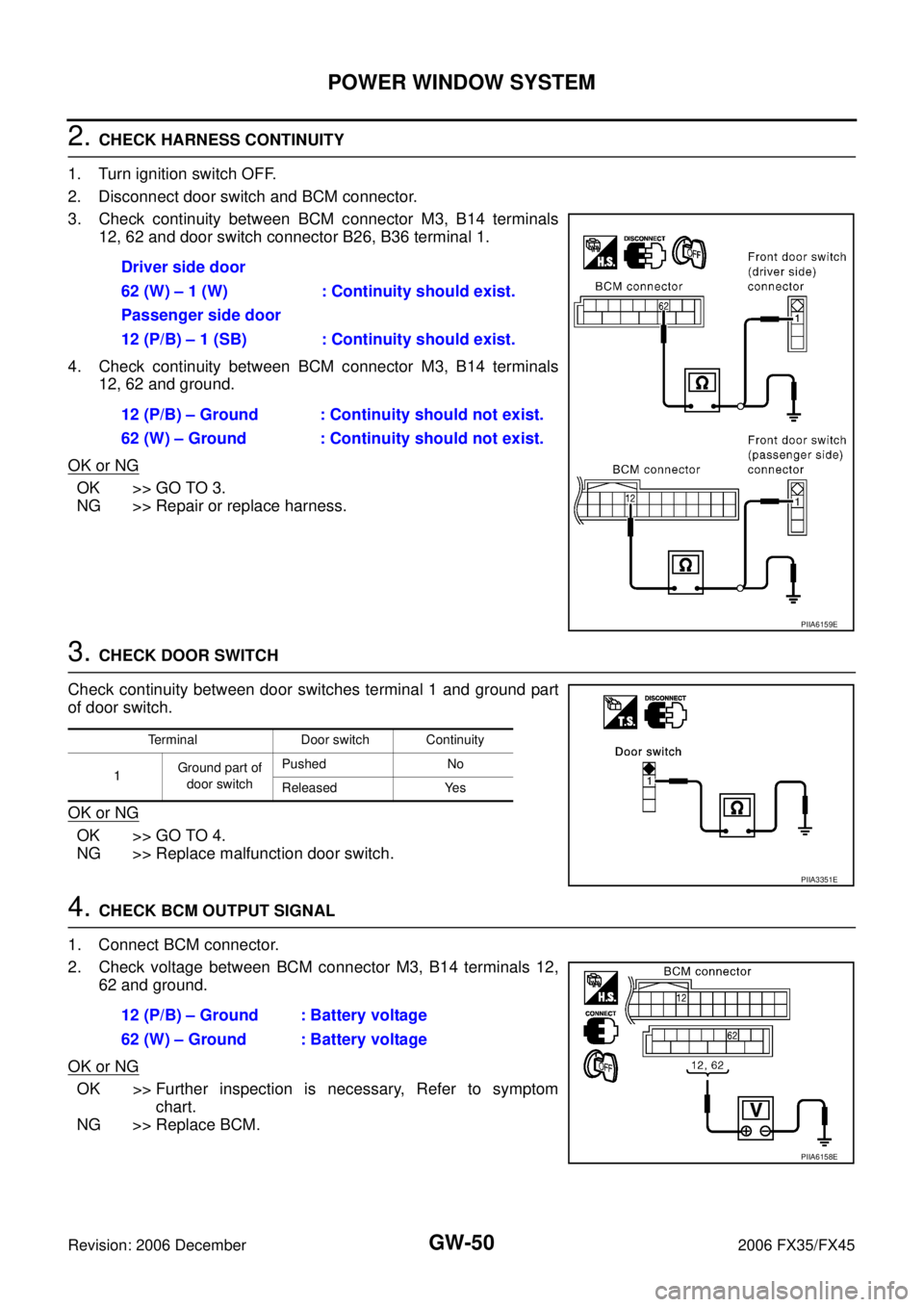
2. CHECK HARNESS CONTINUITY
1. Turn ignition switch OFF.
2. Disconnect door switch and BCM connector.
3. Check continuity between BCM connector M3, B14 terminals 12, 62 and door switch connector B26, B36 terminal 1.
4. Check continuity between BCM connector M3, B14 terminals 12, 62 and ground.
OK or NG
OK >> GO TO 3.
NG >> Repair or replace harness.
3. CHECK DOOR SWITCH
Check continuity between door switches terminal 1 and ground part
of door switch.
OK or NG
OK >> GO TO 4.
NG >> Replace malfunction door switch.
4. CHECK BCM OUTPUT SIGNAL
1. Connect BCM connector.
2. Check voltage between BCM connector M3, B14 terminals 12, 62 and ground.
OK or NG
OK >> Further inspection is necessary, Refer to symptom chart.
NG >> Replace BCM. Driver side door
62 (W) – 1 (W) : Continuity should exist.
Passenger side door
12 (P/B) – 1 (SB) : Continuity should exist.
12 (P/B) – Ground : Continuity should not exist.
62 (W) – Ground : Continuity should not exist.
PIIA6159E
Terminal Door switch Continuity
1 Ground part of
door switch Pushed No
Released Yes
PIIA3351E
12 (P/B) – Ground : Battery voltage
62 (W) – Ground : Battery voltage
PIIA6158E
Page 3291 of 4462
POWER WINDOW SYSTEM GW-51
C
D E
F
G H
J
K L
M A
B
GW
Revision: 2006 December 2006 FX35/FX45
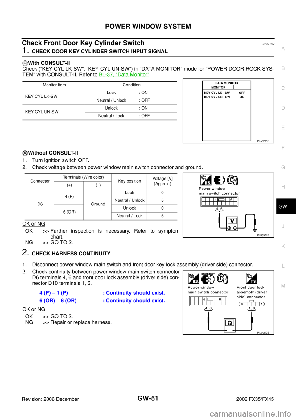
Check Front Door Key Cylinder Switch NIS001RN
1. CHECK DOOR KEY CYLINDER SWITCH INPUT SIGNAL
With CONSULT-II
Check (“KEY CYL LK-SW”, “KEY CYL UN-SW”) in “DATA MONITOR” mode for “POWER DOOR ROCK SYS-
TEM” with CONSULT-II. Refer to BL-37, "
Data Monitor"
Without CONSULT-II
1. Turn ignition switch OFF.
2. Check voltage between power window main switch connector and ground.
OK or NG
OK >> Further inspection is necessary. Refer to symptom chart.
NG >> GO TO 2.
2. CHECK HARNESS CONTINUITY
1. Disconnect power window main switch and front door key lock assembly (driver side) connector.
2. Check continuity between power window main switch connector D6 terminals 4, 6 and front door lock assembly (driver side) con-
nector D10 terminals 1, 6.
OK or NG
OK >> GO TO 3.
NG >> Repair or replace harness.
Monitor item Condition
KEY CYL LK-SW Lock : ON
Neutral / Unlock : OFF
KEY CYL UN-SW Unlock : ON
Neutral / Lock : OFF
PIIA6285E
Connector Terminals (Wire color)
Key position Voltage [V]
(Approx.)
(+) (–)
D6 4 (P)
Ground Lock 0
Neutral / Unlock 5
6 (OR) Unlock 0
Neutral / Lock 5
PIIB3971E
4 (P) – 1 (P) : Continuity should exist.
6 (OR) – 6 (OR) : Continuity should exist.
PIIA4212E
Page 3292 of 4462
GW-52
POWER WINDOW SYSTEM
Revision: 2006 December 2006 FX35/FX45
3. CHECK DOOR KEY CYLINDER SWITCH GROUND
Check continuity between front door lock assembly (driver side) con-
nector D10 terminal 5 and ground.
OK or NG
OK >> GO TO 4.
NG >> Repair or replace harness.
4. CHECK DOOR KEY CYLINDER SWITCH
Check continuity between door lock assembly terminals 1, 6 and 5.
OK or NG
OK >> Further inspection is necessary. Refer to symptom chart.
NG >> Replace front door key cylinder (driver side) switch. 5 (B) – Ground : Continuity should exist.
PIIA4213E
Terminals Key position Continuity
1 5 Lock Yes
Neutral / Unlock No
6 Unlock Yes
Neutral / Lock No
PIIA4214E
Page 3293 of 4462
POWER WINDOW SYSTEM GW-53
C
D E
F
G H
J
K L
M A
B
GW
Revision: 2006 December 2006 FX35/FX45
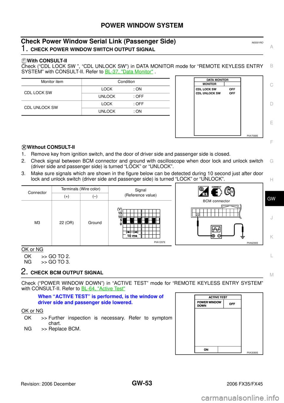
Check Power Window Serial Link (Passenger Side)NIS001RO
1. CHECK POWER WINDOW SWITCH OUTPUT SIGNAL
With CONSULT-II
Check (“CDL LOCK SW ”, “CDL UNLOCK SW”) in DATA MONITOR mode for “REMOTE KEYLESS ENTRY
SYSTEM” with CONSULT-II. Refer to BL-37, "
Data Monitor" .
Without CONSULT-II
1. Remove key from ignition switch, and the door of driver side and passenger side is closed.
2. Check signal between BCM connector and ground with oscilloscope when door lock and unlock switch (driver side and passenger side) is turned “LOCK” or “UNLOCK”.
3. Make sure signals which are shown in the figure below can be detected during 10 second just after door lock and unlock switch (driver side and passenger side) is turned “LOCK” or “UNLOCK”.
OK or NG
OK >> GO TO 2.
NG >> GO TO 3.
2. CHECK BCM OUTPUT SIGNAL
Check (“POWER WINDOW DOWN”) in “ACTIVE TEST” mode for “REMOTE KEYLESS ENTRY SYSTEM”
with CONSULT-II. Refer to BL-64, "
Active Test"
OK or NG
OK >> Further inspection is necessary. Refer to symptom
chart.
NG >> Replace BCM.
Monitor item Condition
CDL LOCK SW LOCK : ON
UNLOCK : OFF
CDL UNLOCK SW LOCK : OFF
UNLOCK : ON
PIIA7068E
Connector Terminals (Wire color)
Signal
(Reference value)
(+) (–)
M3 22 (OR) Ground
PIIA6290EPIIA1297E
When “ACTIVE TEST” is performed, is the window of
driver side and passenger side lowered.
PIIA3080E