Page 4292 of 4462

SRS-44
SIDE CURTAIN AIR BAG MODULE
Revision: 2006 December 2006 FX35/FX45
SIDE CURTAIN AIR BAG MODULEPFP:985P0
Removal and InstallationNHS0007O
REMOVAL
CAUTION:
�Before servicing SRS, turn ignition switch OFF, disconnect both battery cables and wait at least 3
minutes.
�Always work from the side of the side curtain air bag module.
1. Remove headlining. Refer to EI-42, "
Removal and Installation" .
2. Disconnect side curtain air bag connector.
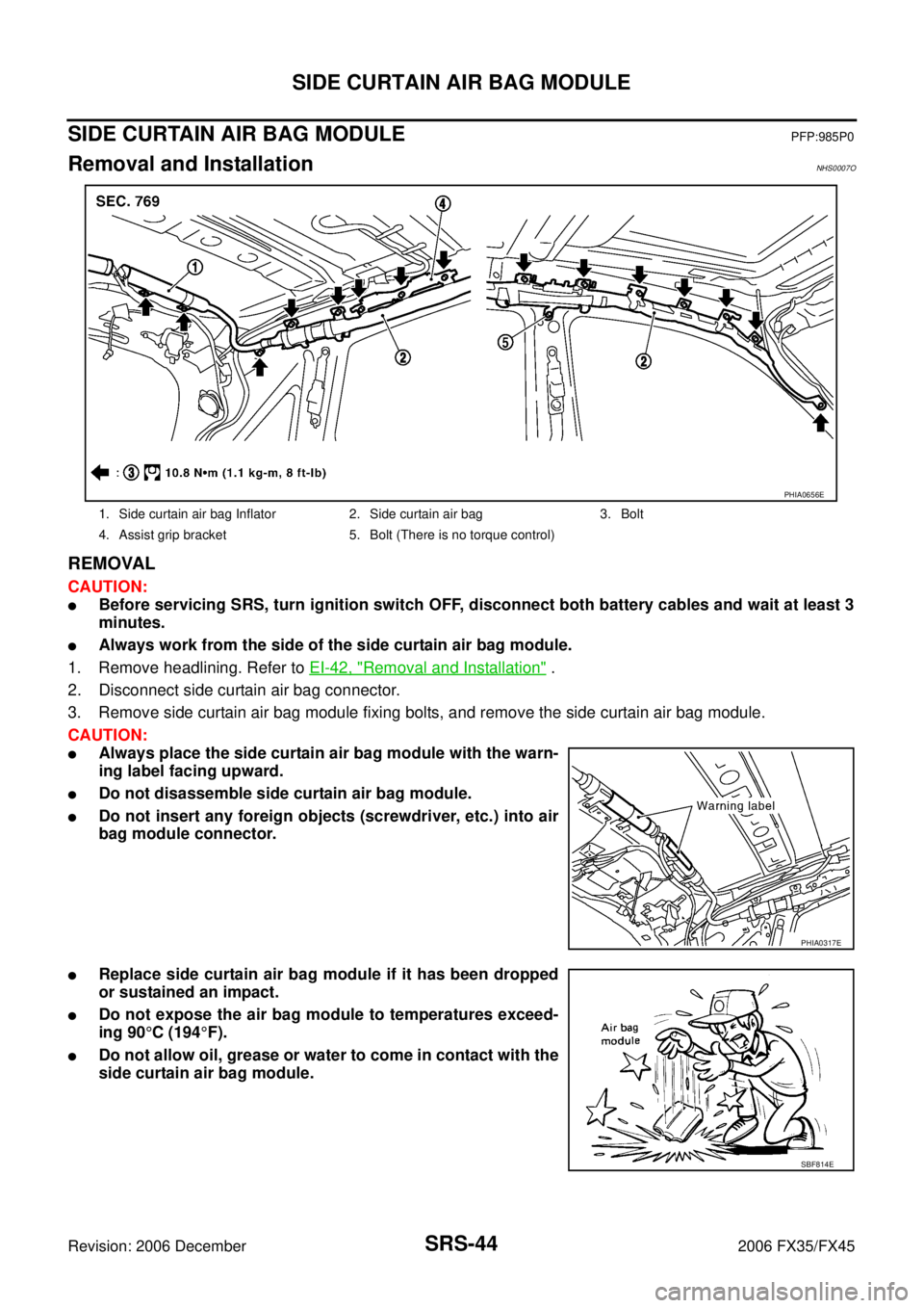
3. Remove side curtain air bag module fixing bolts, and remove the side curtain air bag module.
CAUTION:
�Always place the side curtain air bag module with the warn-
ing label facing upward.
�Do not disassemble side curtain air bag module.
�Do not insert any foreign objects (screwdriver, etc.) into air
bag module connector.
�Replace side curtain air bag module if it has been dropped
or sustained an impact.
�Do not expose the air bag module to temperatures exceed-
ing 90 °C (194 °F).
�Do not allow oil, grease or water to come in contact with the
side curtain air bag module.
1. Side curtain air bag Inflator 2. Side curtain air bag 3. Bolt
4. Assist grip bracket 5. Bolt (There is no torque control)
PHIA0656E
PHIA0317E
SBF814E
Page 4347 of 4462
TRANSFER ASSEMBLY TF-45
C E F
G H
I
J
K L
M A
B
TF
Revision: 2006 December 2006 FX35/FX45
Disassembly and AssemblyNDS000AO
COMPONENTS
1. Drive chain 2. Front drive shaft rear bearing 3. Front drive shaft
4. Front drive shaft front bearing 5. Sprocket 6. Mainshaft
7. Needle bearing 8. Snap ring 9. Mainshaft bearing
10. Front case 11. Front oil seal 12. Mainshaft oil seal
13. Oil cover 14. Temperature sensor 15. Electric controlled coupling
16. Spacer 17. Snap ring 18. O-ring
19. Oil gutter 20. Drain plug 21. Baffle plate
22. Rear bearing 23. Snap ring 24. Spacer
25. Rear oil seal 26. Companion flange 27. Self-lock nut
28. Breather tube 29. Rear case 30. Harness bracket
31. Retainer 32. Filler plug 33. Gasket
PDIA0244E
Page 4356 of 4462
TF-54
TRANSFER ASSEMBLY
Revision: 2006 December 2006 FX35/FX45
4. Install snap ring to rear case. CAUTION:
Do not reuse snap ring.
5. Install mainshaft assembly to rear case, using a drift. CAUTION:
ATF should be applied to contact surface of mainshaft and
rear bearing.
6. Install O-ring to transfer assembly harness connector. CAUTION:
�Do not reuse O-ring.
�Apply ATF to O-ring.
7. Install transfer assembly harness connector into rear case.
8. Install retainer to transfer assembly harness connector.
9. Set temperature sensor and tighten bolt to the specified torque. Refer to TF-45, "
COMPONENTS" .
10. Hold electric controlled coupling harness with oil cover hold plate, install oil cover to rear case, and tighten bolt to the speci-
fied torque. Refer to TF-45, "
COMPONENTS" .
CAUTION:
The harness should be guided by a cut portion.
PDIA0263E
Tool number : ST35321000 ( — )
SDIA2368E
SDIA1597E
SDIA2404E