2006 Hyundai Terracan Air conditioning
[x] Cancel search: Air conditioningPage 407 of 539
1
CONTROLS AND EQUIPMENT
99
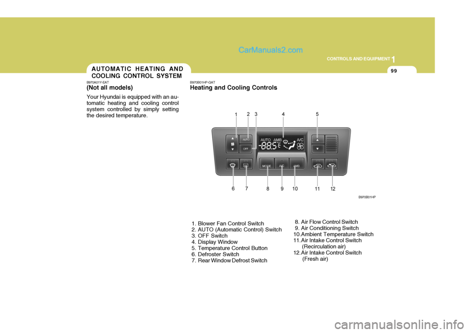
B970B01HP-GAT Heating and Cooling Controls
1. Blower Fan Control Switch
2. AUTO (Automatic Control) Switch
3. OFF Switch
4. Display Window
5. Temperature Control Button
6. Defroster Switch
7. Rear Window Defrost Switch 8. Air Flow Control Switch
9. Air Conditioning Switch
10.Ambient Temperature Switch
11. Air Intake Control Switch (Recirculation air)
12. Air Intake Control Switch (Fresh air)B970B01HPAUTOMATIC HEATING AND COOLING CONTROL SYSTEM
B970A01Y-EAT (Not aII models) Your Hyundai is equipped with an au- tomatic heating and cooling controlsystem controlled by simply setting the desired temperature.
Page 413 of 539
1
CONTROLS AND EQUIPMENT
105
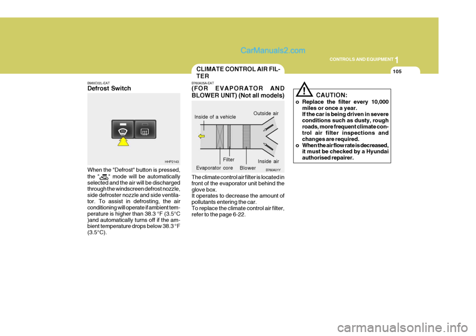
B980C02L-EAT Defrost Switch When the "Defrost" button is pressed, the "
" mode will be automatically
selected and the air will be discharged through the windscreen defrost nozzle, side defroster nozzle and side ventila-tor. To assist in defrosting, the air conditioning will operate if ambient tem- perature is higher than 38.3 °F (3.5°C)and automatically turns off if the am- bient temperature drops below 38.3 °F (3.5°C).
HHP2143 CAUTION:
o Replace the filter every 10,000 miles or once a year. If the car is being driven in severe conditions such as dusty, roughroads, more frequent climate con- trol air filter inspections and changes are required.
o When the air flow rate is decreased, it must be checked by a Hyundaiauthorised repairer.
!
B760A05A-EAT (FOR EVAPORATOR AND BLOWER UNIT) (Not all models) The climate control air filter is located in front of the evaporator unit behind theglove box. It operates to decrease the amount of pollutants entering the car.To replace the climate control air filter, refer to the page 6-22.Inside of a vehicle
Evaporator core B760A01Y
Inside air
Filter
BlowerOutside air
CLIMATE CONTROL AIR FIL- TER
Page 440 of 539
2 DRIVING YOUR HYUNDAI
24
ZC170B1-E Electrical System Winter conditions impose severe de- mands upon vehicle electrical systems, particularly the charging circuit. The battery condition and performance along with the alternator performance and drive belt condition should bechecked prior to the onset of winter.WINTER DRIVING
DC170A1-E The onset of winter conditions subject motor vehicles to greater operating demands. Therefore, the following suggestions will assist in maintainingpeak performance and reliability dur- ing these periods:
o Travel lightly. Don't carry unneces-
sary weight in your car. Weight re- duces fuel economy.
o Don't let the engine idle longer than
necessary. If you are waiting (andnot in traffic), turn off your engine and restart only when you're ready to go.
o Remember, your Hyundai does not require extended warm-up. After theengine has started, allow the engineto run for 10 to 20 seconds prior to placing the vehicle in gear. In very cold weather, however, give yourengine a slightly longer warm-up pe- riod.
o Don't "labour" or "over-rev" the en- gine. Labouring is driving too slowlyin too high a gear resulting in the vehicle kangarooing. If this happens,shift to a lower gear. Over-revving is racing the engine beyond its safe limit. This can be avoided by shiftingat the recommended speeds.
o Use your air conditioning sparingly.
The air conditioning system is oper-ated by engine power so your fuel economy is reduced when you use it.SMOOTH CORNERING
C150A01A-EAT Avoid braking or gear changing in cor- ners, especially when roads are wet. Ideally, corners should always be taken under gentle acceleration. If you followthese suggestions, tyre wear will be held to a minimum.
Page 441 of 539

2
DRIVING YOUR HYUNDAI
25
YC170C1-E Anti-freeze/Corrosion inhibitor The cooling system must always con- tain an Ethylene-Glycol based anti-freeze solution. The system is filled during manufacture with solution of the correct strength which should bechecked before the onset of winter and adjusted or changed as required. NOTE: The anti-freeze solution contains a corrosion inhibitor to prevent deg- radation of the aluminium castingscontained within the engine. There- fore, never, drain the system and refill with water only. In addition, anti-freeze solution must ALWAYS be used in vehicles fittedwith air conditioning, to prevent the heater matrix from freezing and sub- sequently bursting with the refrigera-tion system in use. ZC170D2-E Door Locks Should the door lock mechanism be- come frozen, a proprietary lock de-icershould be used. Never attempt to thaw a frozen door lock using hot water, since the waterwill eventually freeze and compound the problem.
o When driving in extreme condi-
tions, the windscreen wiperblades may fail to clear the screen properly due to the formation ofice upon the blade edge. It will therefore be necessary to peri- odically remove such ice to re-store their efficiency.
o If the power operated door mir-
rors become frozen, attempts toadjust these may damage the mechanism.
o The formation of snow or ice build
up inside the wheel arches mayinterfere with the roadwheels or steering mechanism. In such in-stances, unusual noises or an in- crease in steering effort may re- sult. Therefore, ensure that thewheelarches are checked peri- odically and any accumulated snow or ice removed.
o It is advisable to carry emergency equipment including, torch,shovel, tow rope, blankets etc., ifa journey is to be undertaken into areas of severe road condi- tions.
ZC170E1-E Windscreen Washers & Wipers The windscreen washer bottle should be filled with a solution of water and aproprietary winter screen wash addi- tive. The windscreen wipers should not be used if the blades are frozen tothe windscreen or if they are covered with snow, before this is removed. NOTE: Never allow undiluted screen washer fluid additive to spill upon the paintwork or use engine cool- ant anti-freeze since damage to thepaintwork may result.
Page 450 of 539
3 IN CASE OF EMERGENCY
4
!
1. Ensure that the booster battery is 12
volt type. If the booster battery is installed in another vehicle, ensure that the two vehicles are not touch- ing.
2. Turn off all unnecessary electrical equipment in both vehicles.
3. Ensure that the engine of the ve- hicle providing the jump start is run- ning prior to connection of the jump cables.
4. Connect the red jump cable to the positive (+) terminal of the boosterbattery and the other end to thepositive (+) terminal of the dis- charged battery.
5. Attach the black jump cable to the negative (-) terminal of the boosterbattery, and the other end to a ground point within the engine compartmentof the vehicle with the flat bat-tery. Do not connect to the negative bat- tery terminal of the flat battery sincesparks may be generated with the subsequent risk of explosion.
6. Raise the booster vehicle engine speed to 2,000 r.p.m. and start theengine of the vehicle with the flat battery. 7. Switch "ON" the main beam
headlamps before carefully remov-ing the jumper cables in the reverse order of attachment. Once the jumper cables have been removed,switch "OFF" the main beam headlamps.
CAUTION:
If the jump cables are incorrectly installed, damage to the vehicle elec- trical system may occur, in particu- lar the electronic components suchas the Fuel Injection system com- puter and the Automatic transmis- sion computer. The battery mustnever be disconnected whilst the engine is running.
IF THE ENGINE OVERHEATS
HPD040A2-E If the temperature gauge indicates overheating:
1. Pull off the road and stop as soon as it is safe to do so.
2. Place the gear selector lever in "P"
(automatic), or neutral (manual trans- mission) and set the parking brake. If the air conditioning is on, turn it off.
3. If coolant is running out under the car or steam is coming out from underthe bonnet, stop the engine. Do not open the bonnet until the coolant hasstopped running or the steaming has stopped. If there is no visible loss of coolant and no steam, leave theengine running and check to be sure the engine cooling fan is operating. If the fan is not running, turn theengine off.
4. Check to see if the water pump drive
belt is broken. If it is not missing,check to see that it is tight. If the drive belt seems to be satisfactory, check for coolant leaking from theradiator, hoses or under the car. (If the air conditioning had been in use, it is normal for cold water to bedraining from it).
Page 478 of 539
5VEHICLE MAINTENANCE REQUIREMENTS
10
F070J01A-AAT
o Brake pads, calipers and rotors
Check the pads for excessive wear, discs for run out and wear, and cali- pers for fluid leakage. F070K01A-EAT o Exhaust pipe and sliencer Visually inspect the exhaust pipes, sliencer and hangers for cracks, dete- rioration, or damage. Start the engineand listen carefully for any exhaust gas leakage. Tighten connections or replace parts as necessary. F070L01A-AAT
o Suspension mounting bolts
Check the suspension connections for
looseness or damage. Retighten to the specified torque.
F070M01B-AAT
o Steering gear box, linkage & boots/lower arm ball joint, upper arm ball joint
With the vehicle stopped and engine
off, check for excessive free-play in the steering wheel. Check the linkage for bends or dam-
age. Check the dust boots and ball joints for deterioration, cracks, or dam- age. Replace any damaged parts. F070N01A-AAT
o Power steering pump, belt and hoses
Check the power steering pump and
hoses for leakage and damage. Re- place any damaged or leaking parts immediately. Inspect the power steer-ing belt for evidence of cuts, cracks, excessive wear, oil contamination and proper tension. Replace or adjust it ifnecessary.
F070P01HP-AAT
o Drive shafts and boots
Check the drive shafts, boots and
clamps for cracks, deterioration, ordamage. Replace any damaged partsand, if necessary, repack the grease.
F070Q01A-AAT
o Air conditioning refrigerant
Check the air conditioning lines and
connections for leakage and damage. Check air conditioning performance ac- cording to the relevant shop manual ifnecessary.
Page 479 of 539
Engine Compartment ................................................... 6-2
Daily Operating Checks ............................................... 6-4
Engine Oil ..................................................................... 6-4
Engine Oil and Filter Replacement .............................. 6-8
Engine Coolant Checking and Replacing .................... 6-9
Changing the Air Cleaner Filter ...................................6-12
Manual Transmission Lubricant ..................................6-15
Automatic Transmission Lubricant ..............................6-16
Brake System Checking ............................................. 6-18
Checking the Clutch Fluid ........................................... 6-19
Air Conditioning System Maintenance ........................ 6-20
Changing the Climate Control Air Filter .. ....................6-22
Checking Engine Drive Belts ...................................... 6-24
Fusible Links ............................................................... 6-25
Battery Mai ntenance ................................................... 6-27
Checking Electric Cooling Fans .................................6-29
Power Steering Fluid Level ......................................... 6-29
Fuel Filter ..................................................................... 6-30
Replacing Headlight Bulbs .......................................... 6-31
Headlight Aiming Adjustment ...................................... 6-33
Bulb Wattages ............................................................. 6-35
Fuse Panel D escription ............................................... 6-36
OWNER MAINTENANCE
6
6
Page 487 of 539
6
OWNER MAINTENANCE
9
!
!
engine and ensure that no oil leaks exist. Turn off the engine and aftera couple minutes, recheck the oil level.
CAUTION:
Slowly pour the recommended oil by using a funnel. Do not overfill to prevent engine damage.
WARNING:
Prolonged and repeated contact withused engine oils may result in seri- ous skin disorders including der-matitis and cancer. Avoid contact with skin as far as possible and always wash thoroughly after anycontact. Keep used oils out of reach of children. It is illegal to pollute drains, water courses and soil. Useonly authorisedwaste collection fa- cilities including civic amenity sites and garages for the disposalof used oil and oil filters. If in doubt, contact the local authority for dis- posal instructions. WARNING:
Do not remove the radiator cap when
the engine is hot, since the system is pressurised and coolant may be ejected from the radiator resultingin scalding.
SG050B1-E
Coolant recommendations
Only ethylene glycol based coolant
with a corrosion inhibitor suited toaluminium alloy engine componentsshould be used in the cooling system. No further additives or inhibitors should be used. The coolant specificgravity should be checked as pre- scribed in the maintenance schedule to ensure adequate frost and corro-sion protection. In addition, the en- gine coolant must be replaced at the specified interval since the corrosioninhibitor properties deteriorate with time.
ENGINE COOLANT CHECK- ING AND REPLACING
SG050A1-E
! It is important to note that whilst an increase in the concentration of antifreeze gives an increase in the level of frost protection, a solution which is in excess of 65% anti freeze will resultin reduced frost protection and engine overheating. Therefore the recom- mended concentration of 50% shouldnot be exceeded for general use.The use of methanol based anti freezecompounds may result in engine over-heating and will invalidate the vehicle warranty. NOTE: It is imperative that vehicles fitted with an air conditioning systemhave a coolant concentration of the recommended strength at all times. The use of the air condition-ing system when the cooling sys- tem is filled with water only will result in the heater matrix freezingand subsequently bursting.