Page 308 of 539
YOUR VEHICLE AT A GLANCE
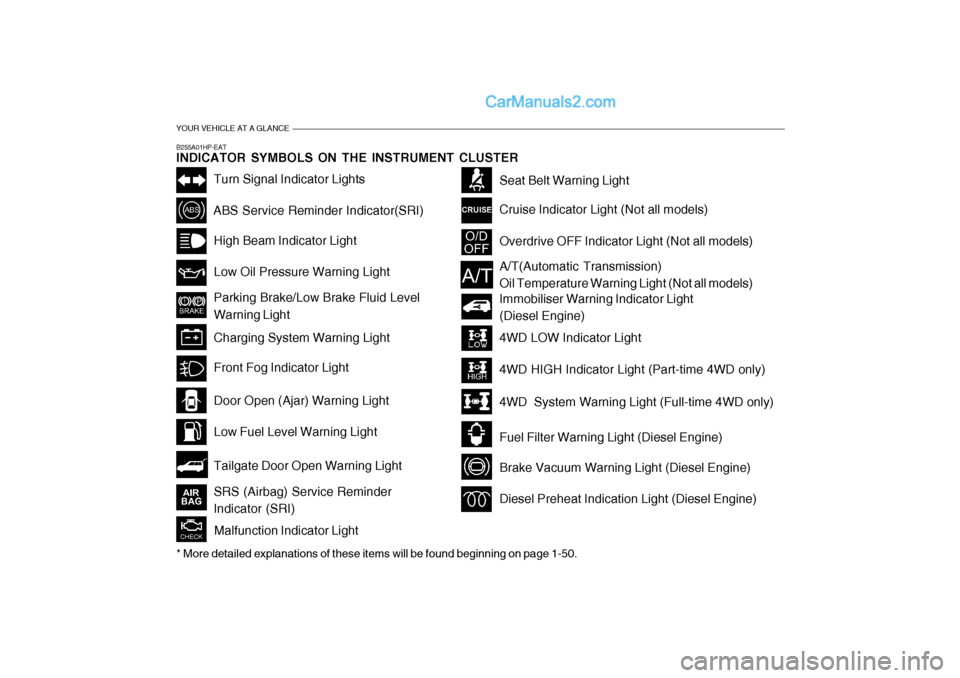
B255A01HP-EAT INDICATOR SYMBOLS ON THE INSTRUMENT CLUSTER
Turn Signal Indicator Lights
ABS Service Reminder Indicator(SRI)High Beam Indicator Light Low Oil Pressure Warning Light Parking Brake/Low Brake Fluid Level Warning Light Charging System Warning Light
Tailgate Door Open Warning Light
Door Open (Ajar) Warning Light Low Fuel Level Warning Light
Front Fog Indicator Light
Overdrive OFF Indicator Light (Not all models)
Immobiliser Warning Indicator Light (Diesel Engine)
Seat Belt Warning Light Cruise Indicator Light (Not all models)
Malfunction Indicator Light
A/T(Automatic Transmission) Oil Temperature Warning Light (Not all models)
4WD LOW Indicator Light 4WD HIGH Indicator Light (Part-time 4WD only)
4WD System Warning Light (Full-time 4WD only)
Fuel Filter Warning Light (Diesel Engine)
Brake Vacuum Warning Light (Diesel Engine)
Diesel Preheat Indication Light (Diesel Engine)
* More detailed explanations of these items will be found beginning on page 1-50.SRS (Airbag) Service Reminder Indicator (SRI)
Page 309 of 539

Fuel Recommendations ............................................... 1-2
Running In Your Hyundai .............................................. 1-4
Immobiliser System ...................................................... 1-5
Door Locks ................................................................... 1-9Anti-theft Alarm System............................................... 1-11
Power Windows ........................................................... 1-14
Seats ........................................................................... 1-16
Seat Belts .................................................................... 1-25
Child Restraint System ................................................ 1-31
Supplemental Restraint (AIRBAG) System .................1-40
Instrument Cluster and Indicator Lights .......................1-46
Warning and Indicator Lights....................................... 1-50
Multi-Function Switch .................................................. 1-60
Windscreen Wiper/Washer Switch ..............................1-63
Sunroof ........................................................................ 1-70
Mirror ........................................................................... 1-75
Bonnet Release ........................................................... 1-83
Cruise Co ntrol.............................................................. 1-87
Heating and Cooling Control .......... ..............................1-90
Stereo Sound System ............................................... 1-106
Antenna ..................................................................... 1-108
CONTROLS AND EQUIPMENT
1
1
Page 311 of 539

1
CONTROLS AND EQUIPMENT
3
ZB010C1-E "Alternative fuels" Fuels which contain methanol or etha- nol must not be used. ZB010D1-E Operation in Foreign Countries Drivers of vehicles which are to be operated in foreign countries must satisfy themselves that:
o The vehicle meets all local regula- tions with respect to insurance, speci- fications etc..
o The correct types and grades of fuel
are available for satisfactory opera-tion of the vehicle.
ZB010F2-A FUELS FOR CLEANER AIR To help contribute to cleaner air, Hyundai recommends that you use fuels treated with detergent additives, which help to prevent deposit forma-tion in the engine. These fuels will help the engines run cleaner and increase the Emission Control System perfor-mance.BEFORE ENTERING THE VE- HICLE
YB020A1-E
o Ensure that all windows, mirrors
and lamps are clean.
o Check condition of all tyres.
o Ensure that no fluid leaks are evi-
dent.
o Ensure that the area around the
vehicle is clear before driving off.AFTER ENTERING THE VE- HICLE
YB020B1-E
o Ensure that all occupants fasten
and correctly adjust seat belts.
o Ensure that seat and head restraint
positions are adjusted for optimum safety, control and comfort.
o Adjust interior and exterior rearview
mirrors.
o Verify correct operation of lamps, horn and other electrical equipment.
o Ensure that warning lamps illumi- nate when ignition is turned on.
NOTE: Fluid levels such as engine oil, en- gine coolant, brake and windscreenwasher fluid should be checked daily or at each refuelling, whichever occurs sooner.
Page 317 of 539
1
CONTROLS AND EQUIPMENT
9
!WARNING:
o Before you drive away, be sure that all the doors are securely closed. It is also recommendedthat the child-protector rear door locks are in the 'lock' position so that children cannot open therear doors from inside the ve- hicle accidentally.
o Before opening the door, always look for and avoid oncoming traf- fic.
o In case of an accident, the door is unlocked automatically(Not allmodels).
DOOR LOCKS
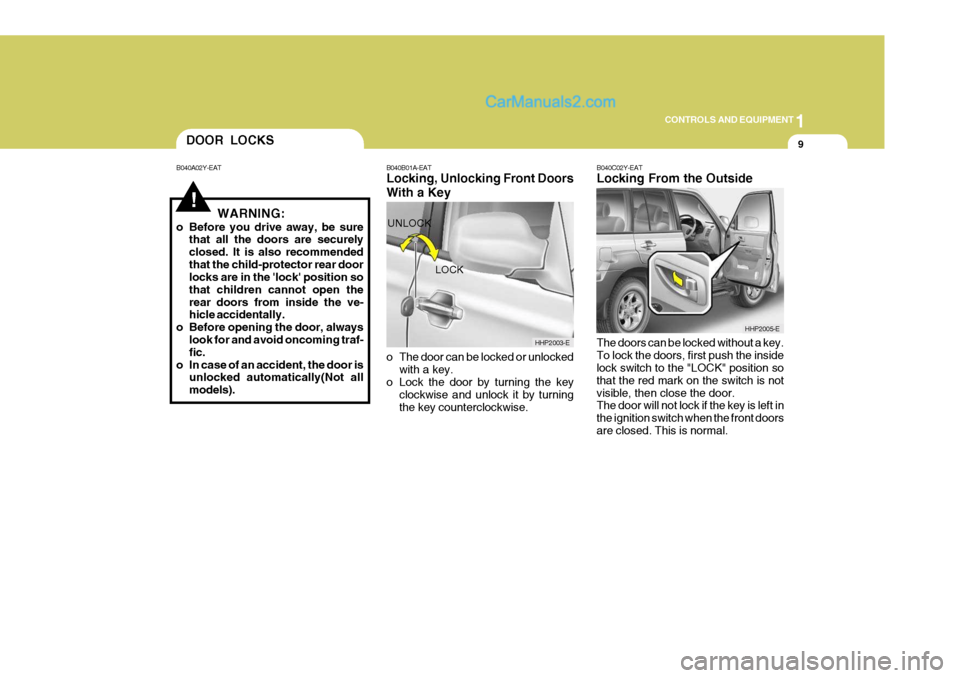
B040A02Y-EAT B040B01A-EAT
Locking, Unlocking Front Doors With a Key
o The door can be locked or unlocked
with a key.
o Lock the door by turning the key
clockwise and unlock it by turning the key counterclockwise. B040C02Y-EAT Locking From the Outside The doors can be locked without a key. To lock the doors, first push the inside lock switch to the "LOCK" position so that the red mark on the switch is notvisible, then close the door. The door will not lock if the key is left in the ignition switch when the front doorsare closed. This is normal.
LOCK
UNLOCK
HHP2003-E
HHP2005-E
Page 323 of 539
1
CONTROLS AND EQUIPMENT
15
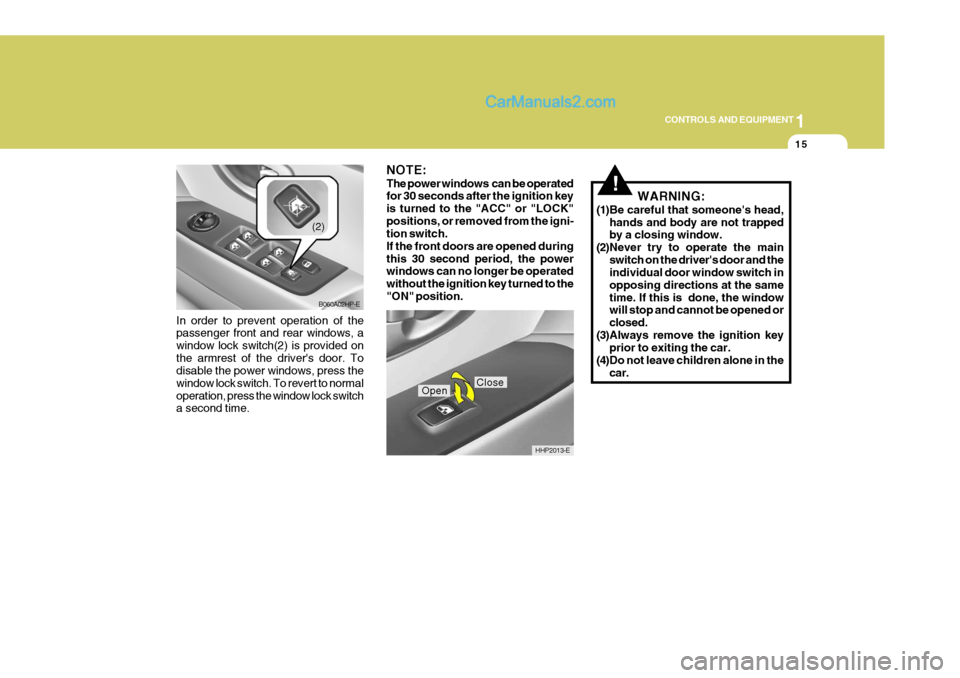
In order to prevent operation of the passenger front and rear windows, a window lock switch(2) is provided onthe armrest of the driver's door. To disable the power windows, press the window lock switch. To revert to normaloperation, press the window lock switch a second time.
B060A02HP-E
(2)
NOTE: The power windows can be operated for 30 seconds after the ignition key is turned to the "ACC" or "LOCK"positions, or removed from the igni- tion switch. If the front doors are opened duringthis 30 second period, the power windows can no longer be operated without the ignition key turned to the"ON" position.
HHP2013-E
CloseOpen
!WARNING:
(1)Be careful that someone's head, hands and body are not trapped by a closing window.
(2)Never try to operate the main
switch on the driver's door and theindividual door window switch in opposing directions at the sametime. If this is done, the window will stop and cannot be opened or closed.
(3)Always remove the ignition key prior to exiting the car.
(4)Do not leave children alone in the car.
Page 324 of 539
1CONTROLS AND EQUIPMENT
16
!WARNING:
Front seat adjustments must not be undertaken whilst the vehicle is in motion. Loss of control of the ve-hicle may result if seat adjustments are made whilst the vehicle is in motion. ZB060A8-E Front Seat Fore/Aft Adjustment
SEATS
SB070A1-E FRONT SEAT ADJUSTMENT
HHP2026-E
!WARNING:
o Seat adjustment should not be made whilst the vehicle is in mo- tion since loss of control of the vehicle may occur.
o To ensure the seat is locked se- curely, attempt to move the seatforward or rearward without usingthe lock release lever.
Front seat fore/aft adjustment is facili-tated by turning the lever located on the front centre of the seat base and sliding the seat forwards or backwards as re-quired. When the seat is at the desired posi- tion, release the lever and ensure thatthe locking mechanism is engaged by rocking the seat to and fro.
Page 325 of 539
1
CONTROLS AND EQUIPMENT
17
!
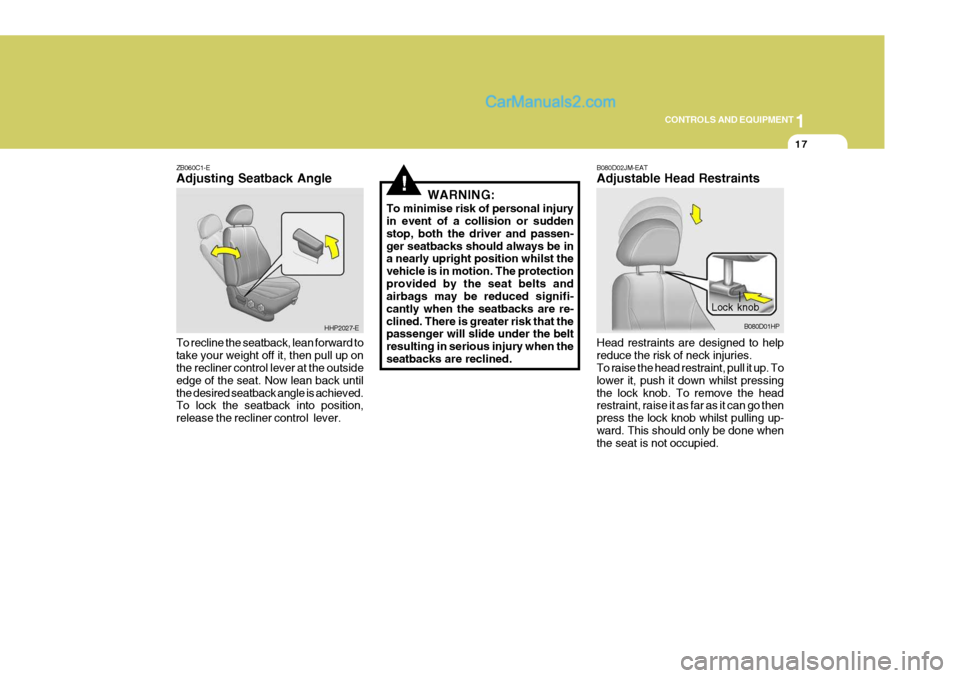
ZB060C1-E Adjusting Seatback Angle To recline the seatback, lean forward to take your weight off it, then pull up on the recliner control lever at the outside edge of the seat. Now lean back untilthe desired seatback angle is achieved. To lock the seatback into position, release the recliner control lever. WARNING:
To minimise risk of personal injury in event of a collision or sudden stop, both the driver and passen-ger seatbacks should always be in a nearly upright position whilst the vehicle is in motion. The protectionprovided by the seat belts and airbags may be reduced signifi- cantly when the seatbacks are re-clined. There is greater risk that the passenger will slide under the belt resulting in serious injury when the seatbacks are reclined.
HHP2027-E
Lock knob
B080D01HP
B080D02JM-EAT Adjustable Head Restraints Head restraints are designed to help reduce the risk of neck injuries. To raise the head restraint, pull it up. To lower it, push it down whilst pressingthe lock knob. To remove the head restraint, raise it as far as it can go then press the lock knob whilst pulling up-ward. This should only be done when the seat is not occupied.
Page 326 of 539
1CONTROLS AND EQUIPMENT
18
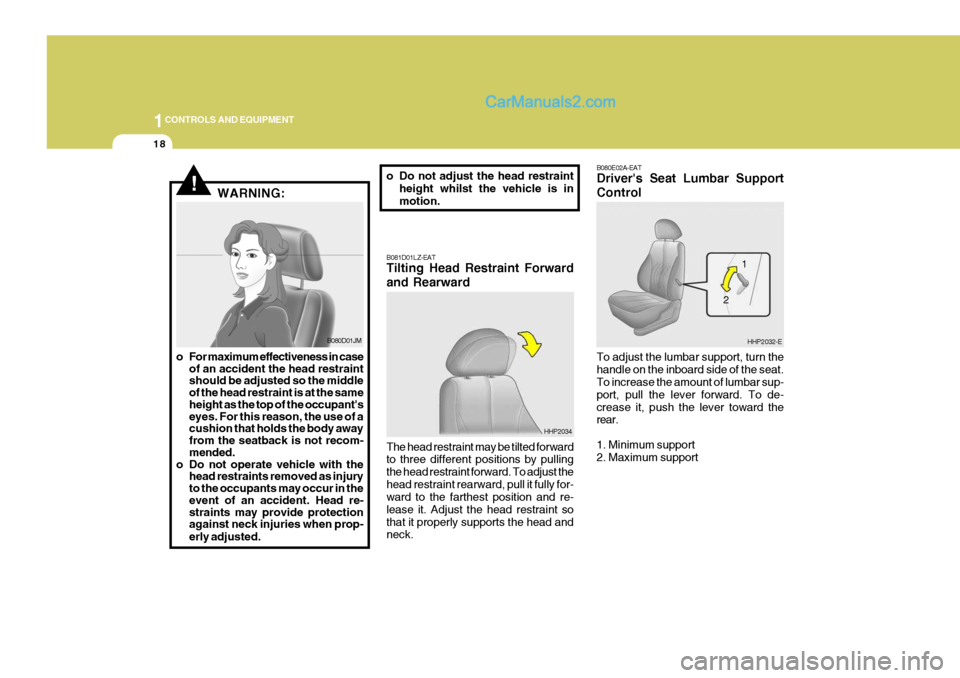
B080E02A-EAT Driver's Seat Lumbar Support Control To adjust the lumbar support, turn the handle on the inboard side of the seat. To increase the amount of lumbar sup- port, pull the lever forward. To de-crease it, push the lever toward the rear. 1. Minimum support 2. Maximum support
HHP2032-E
HHP2034
!WARNING:
B081D01LZ-EAT Tilting Head Restraint Forward and Rearward The head restraint may be tilted forward to three different positions by pulling the head restraint forward. To adjust thehead restraint rearward, pull it fully for- ward to the farthest position and re- lease it. Adjust the head restraint sothat it properly supports the head and neck. 1
2
B080D01JM
o For maximum effectiveness in case of an accident the head restraint should be adjusted so the middle of the head restraint is at the same height as the top of the occupant's eyes. For this reason, the use of a cushion that holds the body away from the seatback is not recom- mended.
o Do not operate vehicle with the head restraints removed as injury to the occupants may occur in the event of an accident. Head re- straints may provide protection against neck injuries when prop- erly adjusted. o Do not adjust the head restraint
height whilst the vehicle is inmotion.