2006 Hyundai Terracan light
[x] Cancel search: lightPage 256 of 539
6
DO-IT-YOURSELF MAINTENANCE
29
G200B02HP-GAT
Replacing Accessory Fuses
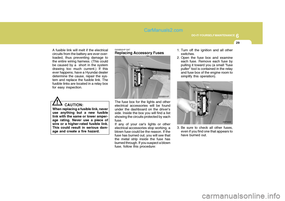
The fuse box for the lights and other
electrical accessories will be found under the dashboard on the driver’s side. Inside the box you will find a list showing the circuits protected by eachfuse. If any of your car's lights or other
electrical accessories stop working, ablown fuse could be the reason. If the fuse has burned out, you will see that the metal strip inside the fuse hasburned through. If you suspect a blown fuse, follow this procedure: G200B01HP
!
A fusible link will melt if the electrical
circuits from the battery are ever over- loaded, thus preventing damage to the entire wiring harness. (This could be caused by a short in the systemdrawing too much current.) If this ever happens, have a Hyundai dealer determine the cause, repair the sys-tem and replace the fusible link. The fusible links are located in a relay box for easy inspection.
CAUTION:
When replacing a fusible link, never use anything but a new fusible link with the same or lower amper-age rating. Never use a piece of wire or a higher-rated fusible link. This could result in serious dam-age and create a fire hazard. 3. Be sure to check all other fuses,
even if you find one that appears tohave burned out.
1. Turn off the ignition and all other
switches.
2. Open the fuse box and examine each fuse. Remove each fuse bypulling it toward you (a small "fusepuller" tool is contained in the relay and fuse box of the engine room to simplify this operation).
HHP4002
Page 257 of 539
6 DO-IT-YOURSELF MAINTENANCE
30
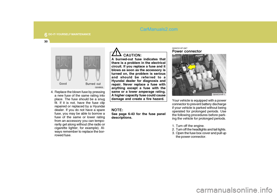
4. Replace the blown fuse by pressing
a new fuse of the same rating into place. The fuse should be a snugfit. If it is not, have the fuse clip repaired or replaced by a Hyundai dealer. If you do not have a sparefuse, you may be able to borrow a fuse of the same or lower rating from an accessory you can tempo-rarily get along without (the radio or cigarette lighter, for example). Al- ways remember to replace the bor-rowed fuse. Good
G200B02L
Burned out CAUTION:
A burned-out fuse indicates thatthere is a problem in the electricalcircuit. If you replace a fuse and it blows as soon as the accessory is turned on, the problem is seriousand should be referred to a Hyundai dealer for diagnosis and repair. Never replace a fuse withanything except a fuse with the same or a lower amperage rating. A higher capacity fuse could causedamage and create a fire hazard. NOTE: See page 6-43 for the fuse panel descriptions.
! G200C01HP-GAT
Power connector
Your vehicle is equipped with a power connector to prevent battery discharge if your vehicle is parked without being operated for prolonged periods. Usethe following procedures before park- ing the vehicle for prolonged periods.
1. Turn off the engine.
2. Turn off the headlights and tail lights.
3. Open the fuse box cover and pull up the power connector.
G200C01HP-1
Page 258 of 539
6
DO-IT-YOURSELF MAINTENANCE
31CHECKING THE BATTERY
!
G210A01A-AAT
WARNING:
Batteries can be dangerous! When
working with batteries, carefully observe the following precautionsto avoid serious injuries. o If battery fluid is on your skin, flush
the affected areas with water for atleast 15 minutes and then seek medical assistance.
o If battery fluid is in your eyes, rinse out your eyes with water and getmedical assistance as soon as possible. While you are being drivento get medical assistance, continue to rinse your eyes by using a sponge or soft cloth saturated withwater.
o If you swallow battery fluid, drink a large quantity of water or milk fol- lowed by milk of magnesia, eat a raw egg or drink vegetable oil. Getmedical assistance as soon as possible.
While batteries are being charged (either by a battery charger or by thevehicle's alternator), they produce explosive gases. Always observe these warnings to prevent injuries fromoccurring:
o Charge batteries only in a well ven- tilated area.
o Do not permit flames, sparks or smoking in the area.
o Keep children away from the area.
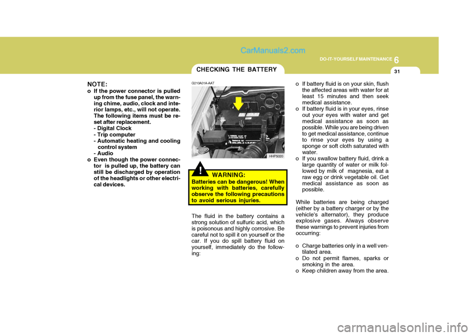
The fluid in the battery contains a
strong solution of sulfuric acid, whichis poisonous and highly corrosive. Becareful not to spill it on yourself or the car. If you do spill battery fluid on yourself, immediately do the follow-ing: HHP5020
NOTE:
o If the power connector is pulled up from the fuse panel, the warn-ing chime, audio, clock and inte- rior lamps, etc., will not operate. The following items must be re-set after replacement.- Digital Clock - Trip computer
- Automatic heating and cooling
control system
- Audio
o Even though the power connec- tor is pulled up, the battery can still be discharged by operation of the headlights or other electri-cal devices.
Page 259 of 539
6 DO-IT-YOURSELF MAINTENANCE
32
!
G210B01Y-GET
Checking the Battery
Keep the battery clean. Any evidence
of corrosion around the battery posts or terminals should be removed using a solution of household baking sodaand warm water. After the battery terminals are dry, cover them with a light coating of grease.
WARNING:Always read the followinginstructions carefullywhen handling a battery.Keep lighted cigarettesand all other flames orsparks away from the bat- tery. Hydrogen, which is a highly combustible gas, is always present in batterycells and may explode if ignited.Keep batteries out of the reach of children because batteries contain highly corrosive SULFURIC ACID.Do not allow battery acid to contact your skin, eyes, clothing or paint finish.If any electrolyte gets intoyour eyes, flush your eyeswith clean water for at least 15 minutes and get imme- diate medical attention. Ifpossible, continue to ap- ply water with a sponge or cloth until medical atten-tion is received.If electrolyte gets on yourskin, thoroughly wash thecontacted area.If you feel a pain or a burn-ing sensation, get medi- cal attention immediately. Wear eye protection when charging or working near a battery. Always provide ventilation when working in an en- closed space.o When lifting a plastic-cased bat- tery, excessive pressure on the case may cause battery acid toleak, resulting in personal in- jury. Lift with a battery carrier or with your hands on oppositecorners.
o Never attempt to charge the bat- tery when the battery cables are connected.
o The electrical ignition system works with high voltage. Never touch these componentswith the engine running or the ignition switched on.
Page 265 of 539

6 DO-IT-YOURSELF MAINTENANCE
38REPLACING HEADLIGHT BULBS
G260A03A-GAT Before attempting to replace a head- light bulb, be sure the switch is turned to the "OFF" position. The next paragraph shows how to reach the headlight bulbs so they may be changed. Be sure to replacethe burned-out bulb with one of the same number and wattage rating.
CAUTION:
o Keep the lamps out of contact with petroleum product, such as oil, gasoline, etc.
o After heavy, driving rain or wash- ing, headlight and taillight lensescould appear frosty. This condi- tion is caused by the temperature difference between the lamp in-side and outside. This is similar to the condensation on your win- dows inside your vehicle duringthe rain and doesn’t indicate a problem with your vehicle. If the water leaks into the lamp bulbcircuitry, have the vehicle checked by an Authorized Hyundai Dealer.
! G270A01B-GAT
Headlight Bulb
1. Allow the bulb to cool. Wear eye
protection.
2. Open the engine hood.
3. Always grasp the bulb by its plas- tic base, avoid touching the glass.
4. Using a spanner, remove the head- light assembly mounting bolts.
5. Disconnect the power cord from the bulb base in the back of the headlight.
G270A01HP7. Disconnect the connector from the
bulb base in the back of the head- light.
G270A02HP
6. Turn the plastic cover counterclock- wise and remove it. 8. Push the bulb spring to remove the
headlight bulb.
Page 266 of 539
6
DO-IT-YOURSELF MAINTENANCE
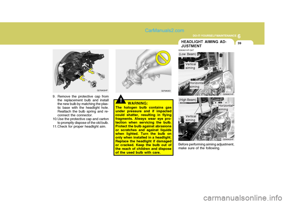
39HEADLIGHT AIMING AD- JUSTMENT
G290A01HP-GAT
G290A01HP G290A02HP
Before performing aiming adjustment, make sure of the following.
!WARNING:
The halogen bulb contains gas
under pressure and if impacted could shatter, resulting in flyingfragments. Always wear eye pro- tection when servicing the bulb. Protect the bulb against abrasionsor scratches and against liquids when lighted. Turn the bulb on only when installed in a headlight.Replace the headlight if damaged or cracked. Keep the bulb out of the reach of children and disposeof the used bulb with care.
G270A03HP
9. Remove the protective cap from the replacement bulb and install the new bulb by matching the plas- tic base with the headlight hole.Reattach the bulb spring and re- connect the connector.
10.Use the protective cap and carton to promptly dispose of the old bulb.
11.Check for proper headlight aim. G270A03O(Low Beam)
(High Beam)
Vertical aiming
Horizontal aiming
Vertical aiming
Horizontal aiming
Page 267 of 539
6 DO-IT-YOURSELF MAINTENANCE
40
1. Keep all tires inflated to the correct
pressure.
2. Place the vehicle on level ground and press the front bumper & rear bumper down several times. Placevehicle at a distance of 3m (118.1 in.) from the test wall.
3. See that the vehicle is unloaded (except for full levels of coolant, engine oil and fuel, and spare tire,jack, and tools). Have the driver or equivalent weight placed in driver's seat.
4. Clean the headlight lens and turn on the headlight.
5. Open the hood.
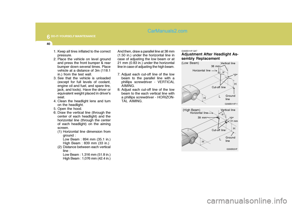
6. Draw the vertical line (through the center of each headlight) and thehorizontal line (through the center of each headlight) on the aiming screen.
(1) Horizontal line dimension from
ground : Low Beam : 894 mm (35.1 in.) High Beam : 839 mm (33 in.)
(2) Distance between each vertical line : Low Beam : 1,316 mm (51.8 in.) High Beam : 1,076 mm (42.4 in.) And then, draw a parallel line at 38 mm
(1.50 in.) under the horizontal line incase of adjusting the low beam or at 21 mm (0.83 in.) under the horizontal line in case of adjusting the high beam.
7. Adjust each cut-off line of the low beam to the parallel line with a phillips screwdriver - VERTICAL AIMING.
8. Adjust each cut-off line of the low beam to the each vertical line witha phillips screwdriver - HORIZON-TAL AIMING. G290B01HP-GAT
Adjustment After Headlight As- sembly Replacement
G290B02HP
LW
H Cut-off line
"P"
Vertical line
Horizontal line
Ground line
21 mm39 mm
(High Beam)
H
G290B01HP-1
LW
"P"
38 mm
H
H
(Low Beam)
Vertical line
Ground line
Cut-off line
Horizontal line
Page 268 of 539
6
DO-IT-YOURSELF MAINTENANCE
41
"W" Distance between each headlight center :Low Beam : 1,316 mm (51.8 in.) High Beam : 1,076 mm (42.4 in.) "L" Distance between the headlightsand the wall that the lights are tested against : Low Beam : 3,000 mm (118.11 in.) High Beam : 3,000 mm (118.11in.)
If the vehicle has had front body repair
and the headlight assembly has beenreplaced, the headlight aiming should be checked using an aiming screen as shown in the illustration. Turn on theheadlight switch. (Low Beam or High Beam Position).
1. Adjust headlights so that main axis of light is parallel to center line of the body and is aligned with point "P" shown in the illustration.
2. Dotted lines in the illustration show the center of headlights. "H" Horizontal center line of headlightsfrom ground :Low Beam : 894 mm (35.1 in.) High Beam : 839 mm (33 in.)