Page 340 of 484
BE-62
Diagram of acoustical equipment system (continued)
SL SK
SY SJ
fuse ignition switch
ACC ON ST41
small lamp
large lamp
662
5
9
PQ813O57
receiver receiver
12 3
4
56
78912
3454
32 1
5
6 7 8
ignition switch
combined switch
8765
16 15 14
NP12 1143 2
1
9 10
fuse ignition switch
ACC
ONST41
small lamp
large lamp
616
25
934
81
32 5 7
CD device CD device
12 34
567
U912
345
ignition switch
43 21
R6 8
combined switch
8765
16NR14 13 12 11 10 92 3 4N
receiver
small lamp relaysmall lamp relayelectric aerialCD device
batterybattery
fuse
fuse
7
Body Electric System�Acoustical Equipment System
Page 347 of 484
BE-69
SL SK SY SJ
1 connected to cab wire harness
2 connected to cab wire harness
3 odometer sensor
4 back-up lamp switch
5 turn lamp on right side
6 grounding wire
7 brush motor
8 protective box II
9 wire connecting with accumulator anode
10 wire connecting with accumulator anode
11 electromagnetic fan
12 washer motor
13 right fog lamp
14 right turn lamp
15 right headlamp
16 right small lamp17 horn electric horn
18 left turn lamp
19 left small lamp
20 left headlamp
21 left fog lamp
22 pressure switch of air-conditioner
23 generator
24 generator
25 grounding wire
26 turn lamp on left side
27 brake liquid level sensor
28 connected to cab wire harness
29 connected to cab wire harness
30 connected to cab wire harness
31 flasher relay
1
O
3
4
5
6
7
8
9
10
11
12
13
14
151617
18
19
20 21222324252627282930
31
Housing wire harness (continued)
Body Electric System�Wire Harness Distribution
Page 348 of 484
")
BE-70
SF
1
2 P
4 5 6
7
8 9 10
11 12 13
14
15 16 1718 19
20
21
22
23
2425262728
29
30 3132
33
34
3536
37
38
39
40
41
42
43
44 45 46 47
48
49 50 51
52
53
54
555657 5859
Housing wire harness (continued)
60 61
1 left door lamp switch
2 defrost switch at tail door
3 window regulator at tail door
4 parking brake switch
5 ignition lock
6 combined switch
7 instrument
8 combined switch shell
9 grounding wire
10 amplifying plate of air-conditioner
11 heat-sensitive resistance
12 control panel of air-conditioner
13 A/C Switch
14 glove-box lamp switch
15 glove-box lamp
16 speed-adjusting resistance
17 blower
18 indoor temperature sensor
19 right front loudspeaker
20 brush motor
21 turn lamp on right side22 electric fan relay
23 maxi-fuse
24 joint of wire harness at right front door
25 right front door lamp switch
26 right electric back-up mirror
27 grounding wire
28 rear sound box wire
29 ashtray lamp
30 CD Device wire
31 cigarette lighter A
32 cigarette lighter B
33 dual flasher switch
34 fog lamp switch
35 temperature indicator
36 stop lamp switch
37 brake liquid level sensor
38 control case of central control lock
39 left front loudspeaker
40 automatic aerial
41 turn lamp on left side
42 generator43 left front conner lamp
44 left front lever-shaped lamp
45 front fog lamp
46 left headlamp
47 temperature control switch
48 connected to wire of 220
49 spraying motor A
50 spraying motor B
51 right front conner lamp
52 right headlamp
53 horn A
54 horn B
55 right front lever-shaped lamp
56 right front fog lamp
57 electric fan
58 outdoor temperature sensor
59 connected to chassis wire harness
anright central wire harness
60 connected to left central wire harness
61 connected to engine wire harness
Body Electric System�Wire Harness Distribution
Page 351 of 484

BE-73
SY SJ
1 grounding wire
2 wire harness at right front door
3 warm air motor
4 connected to wire harness at right front door
5 control case of central control lock
6 electric aerial
7 heat-sensitive resistance
8 speed-adjusting resistance
9 connected to housing wire harness
10 connected to housing wire harness
11 A/C switch
12 air-volume switch
13 ashtray luminous lamp
14 grounding wire
15 ECU
16 CD device
17 CD device
18 cigarette lighter
19 cigarette lighter grounding wire
20 cigarette lighter luminous lamp
21 combined switch
22 fog lamp switch
23 dual flasher switch
24 rear defroster switch
25 rear brush switch
26 rear washer switch27 combination instrument
28 combination instrument
29 stop lamp switch
30 roof wire harness
31 connected to housing wire harness
32 connected to housing wire harness
33 connected to housing wire harness
34 connected to wire harness at left front door
35 connected to wire harness at left front door
36 connected to wire harness at left front door
37 protective box
38 rear defrost relay
39 connected to wire harness of rear air-conditioner
40 grounding wire
41 parking brake switch
42 connected to chassis wire harness
43 wire harness at right rear door
44 right front door lamp switch
45 right rear loudspeaker
46 rear washer motor
47 connected to wire harness at tail door
48 left front door lamp switch
49 wire harness at left rear door
50 left rear loudspeaker
51 standby power seat
1
2
3
4
5
6
7
8
9
101112
13
14
15
1617
181920
21 22232425262728
29
30
31
32
3334
35
36
37
38
39
4041 4243 444546
47
48495051
Cab wire harness (continued)
Body Electric System�Wire Harness Distribution
Page 358 of 484
BE-80
Wire harness at tail door and of rear air-conditioner
SY SJ
wire harness of rear
air-conditionerwire harness
of rear brush
1
2
3456
7
8V 10 1112 13
NQ
Only the vehicle with SY model has the wire harness of rear air-conditioner shown in above-mentioned wire harness.
1 rear A/C switch
2 connected to cab wire harness
3 rear air-conditioning relay
4 grounding wire
5 temperature control switch
6 electromagnetic valve
7 temperature controller8 speed-adjusting resistance
9 license lamp
10 license lamp
11 rear brusher motor
12 defroster
13 defroster
14 connected to cab wire harness
Body Electric System�Wire Harness Distribution
Page 367 of 484
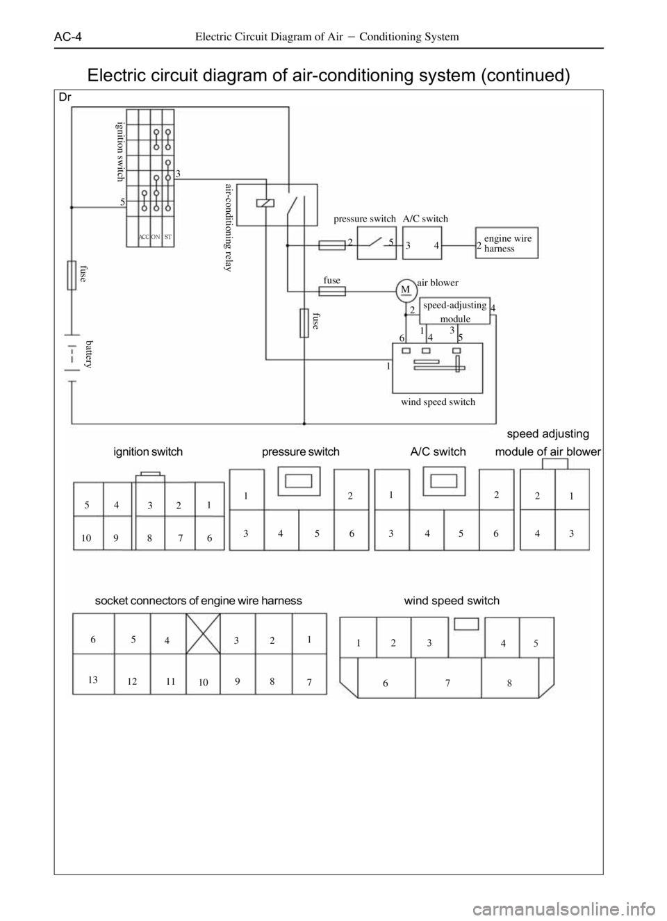
AC-4Electric Circuit Diagram of Air�Conditioning System
Electric circuit diagram of air-conditioning system (continued)
Dr
fuseA/C switch pressure switch
engine wire
harness
air blower
speed-adjusting
module
wind speed switch M2 2
2
2 2
2
2
O 24 4 4 4
4
Q 4
44 3 3
3
3 3 3 3
3
P 5 5
5
5 5 5
5
R 1
1
N 1
1
1
1
N6
6 6
6
6
S 7
7
TU 8
8 9
9 10
10 11 12 13
ignition switch pressure switchA/C switchspeed adjusting
module of air blower
socket connectors of engine wire harnesswind speed switch
lk ^`` p q
fuse ignition switchair-conditioning relayfuse
battery
Page 368 of 484
AC-5Electric Circuit Diagram of Air�Conditioning System
SF
ST
fusethree-state pressure switch
cold-hot
servomotor circular
servomotor mode
servomotor main air-conditioning
control panel
speed
adjusting
module
air blower
b`r
power resistor
water
valve
Mjjj
M
ACCON
+12V 5
R R 5
5 5 5 5
5
5 PP
P P 3
3
3 3 3 3
3
3
3 1
111
1
1
1 N
N N
1
2 2 2 2
2
22 O O OO
4
44 4
4 4 4Q
Q
Q Q
4
6 6
6 6 6
6S S 6
S6
7
7
7 8
88 9
9
9 10
1010
1111
12
13 14 15 16 17 18 1920
20 21 22 23 2423
ignition switch modular air-door motor cold-hot air-door motor air-in motor
three-stage
pressure switch speed adjusting
modul air conditioning
ignition switchsmall light relay
fusefuse electronic fan
water temperature relay
fuse
compressor relayelectromagnetic
fan relay
compressor clutch
24
Electric circuit diagram of air-conditioning system (continued)
battery
18
5
17
16
3
15
19
14
22
1
13
Page 369 of 484
AC-6Air-Conditioning System�(Electric Circuit Diagram)
�S
SL SK SJ
fuse
air-conditioning
request relay
connect with ECUfuseECU
^``lkpq
4
5
1
2
45 6
32
36 54
21
1
2 1
32
ignition switch speed adjusting module
air blower A/C SWITCH pressure switch
1 2 3 4
5 6 7 81 2 3
4 5 61 2 3
4 5 6
1
2 1
2 3 1
2
compressor
electromagnetic fan relay compressor relay
pressure switch fuse
fuse
electromagnetic fan
air-conditioning
request relay
A/Cswitch
blower
air-volume switch
speed-adjusting resistance
heat-sensitive resistance blower relay
charging indicating lamp
ignition switch
air-volume switch Electric circuit diagram of air-conditioning system (continued)
battery
ECU

SL SK
SY SJ
fuse ignition switch
ACC ON ST41
small lamp
large lamp
662
5
9
PQ813O57
receiver receiver
12 3
4
56
78912
3454
32 1
5
6 7 8
ignitio")