Page 438 of 484

B0-55Vehicle Body�Instrument Panel
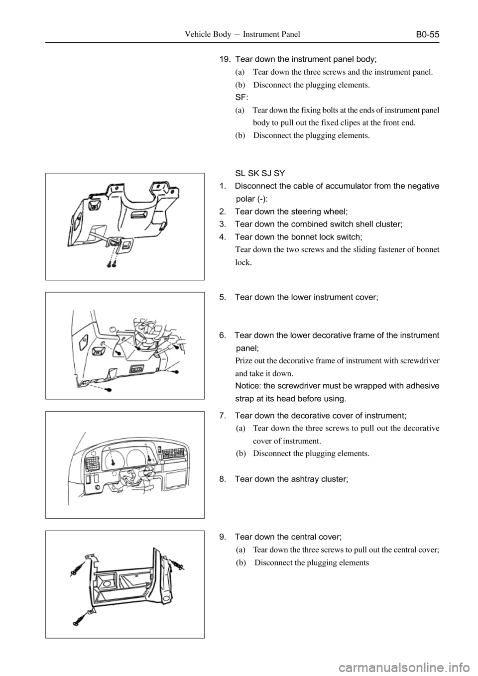
19. Tear down the instrument panel body;
(a) Tear down the three screws and the instrument panel.
(b) Disconnect the plugging elements.
SF:
(a) Tear down the fixing bolts at the ends of instrument panel
body to pull out the fixed clipes at the front end.
(b) Disconnect the plugging elements.
SL SK SJ SY
1. Disconnect the cable of accumulator from the negative
polar (-):
2. Tear down the steering wheel;
3. Tear down the combined switch shell cluster;
4. Tear down the bonnet lock switch;
Tear down the two screws and the sliding fastener of bonnet
lock.
5. Tear down the lower instrument cover;
6. Tear down the lower decorative frame of the instrument
panel;
Prize out the decorative frame of instrument with screwdriver
and take it down.
Notice: the screwdriver must be wrapped with adhesive
strap at its head before using.
7. Tear down the decorative cover of instrument;
(a) Tear down the three screws to pull out the decorative
cover of instrument.
(b) Disconnect the plugging elements.
8. Tear down the ashtray cluster;
9. Tear down the central cover;
(a) Tear down the three screws to pull out the central cover;
(b) Disconnect the plugging elements
Page 442 of 484

B0-59Body�Safety Belt
Safety belt
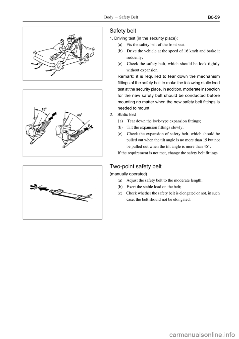
1. Driving test (in the security place);
(a) Fix the safety belt of the front seat.
(b) Drive the vehicle at the speed of 16 km/h and brake it
suddenly;
(c) Check the safety belt, which should be lock tightly
without expansion.
Remark: it is required to tear down the mechanism
fittings of the safety belt to make the following static load
test at the security place, in addition, moderate inspection
for the new safety belt should be conducted before
mounting no matter when the new safety belt fittings is
needed to mount.
2. Static test
�a) Tear down the lock-type expansion fittings;
(b) Tilt the expansion fittings slowly;
(c) Check the expansion of safety belt, which should be
pulled out when the tilt angle is no more than 15 but not
be pulled out when the tilt angle is more than 45�.
If the requirement is not met, change the safety belt fittings.
Two-point safety belt
(manually operated)
(a) Adjust the safety belt to the moderate length;
(b) Exert the stable load on the belt;
(c) Check whether the safety belt is elongated or not, in such
case, the belt should not be elongated.
Page 449 of 484
B0-66Body�Reserve Tire Bracket
Reserve tire bracket (�)
Element figure
reserve tire holderbuffer block bracket
buffer block
lock clip bracket
assembly
return spring reserve tire bracket adjusting arm
reserve tire lock
90
SY
�specified torque
reserve tire bracket reserve tire holderreserve tire lock
lock clip bracket assembly
adjusting arm
SJ
90
KN�m
Page 450 of 484

B0-67Vehicle Body�Reserve Tire Bracket
Reserve tire bracket (�)
Element figure
buffer blockspringy welt
trim cover of fixed bracket
decorative cover of screw hole reserve tire bracket
nut
SF
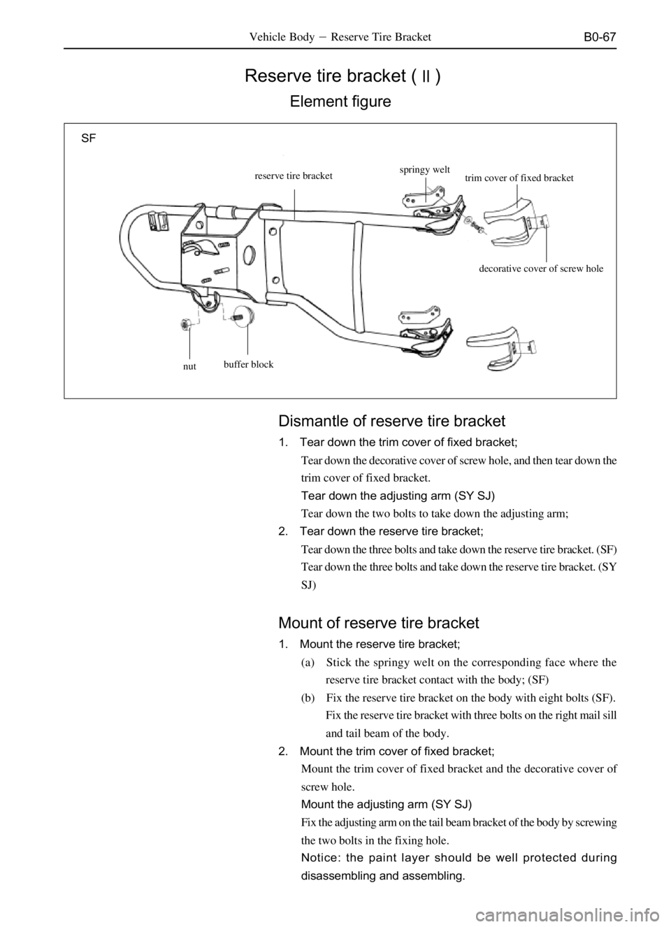
Dismantle of reserve tire bracket
1. Tear down the trim cover of fixed bracket;
Tear down the decorative cover of screw hole, and then tear down the
trim cover of fixed bracket.
Tear down the adjusting arm (SY SJ)
Tear down the two bolts to take down the adjusting arm;
2. Tear down the reserve tire bracket;
Tear down the three bolts and take down the reserve tire bracket. (SF)
Tear down the three bolts and take down the reserve tire bracket. (SY
SJ)
Mount of reserve tire bracket
1. Mount the reserve tire bracket;
(a) Stick the springy welt on the corresponding face where the
reserve tire bracket contact with the body; (SF)
(b) Fix the reserve tire bracket on the body with eight bolts (SF).
Fix the reserve tire bracket with three bolts on the right mail sill
and tail beam of the body.
2. Mount the trim cover of fixed bracket;
Mount the trim cover of fixed bracket and the decorative cover of
screw hole.
Mount the adjusting arm (SY SJ)
Fix the adjusting arm on the tail beam bracket of the body by screwing
the two bolts in the fixing hole.
Notice: the paint layer should be well protected during
disassembling and assembling.
Page 457 of 484
B0-74
Body Dimension
Rear Wall (�)
Vehicle Body�Body Dimension
Mark NameBore diameterMark NameBore diameter
J�,j�Connecting part of outer panel of
rear wall with roof�O�,o�Corresponding spots of upper edge
�
K�,k�Lower edge of outer panel of rear
wall�P�,p�Vertical corresponding spot of
floor�
L�,l�Lines and angle of rear side wall
�Q�,q��
M�,m�Upper angle of rear lamp cavity
�R�,r�Outer edge of lock box at tailgate
�
N�,n�Lower angle of rear lamp cavity
�
J�
k� K� 1022j�
1270 1202
376
SY SJ
(point size in 3D)
GN O�o
m� Q�q
N�
n�
P�p
R�r M�900 L�
1042
1376 1141l�
*1: SY 1376
SJ 1385
SF
(point size in 3D)
Page 474 of 484

A-2
Clutch
Specification
Item Specification
Fastening torque for clutch tube on master cylinder
Fastening torque for clutch tube on wheel-brake cylinder
Fastening torque for clutch pressure plate160
190-200
5-15
0.3
0.8
0.2
0.6
5
Max misplacement�0.5 Pedal height (calculated from front wall
Pedal free stroke
Min depth of clutch-facing rivet
Max radial swing difference of clutch rib
Max radial swing difference of flywheel
Max width of wear of diaphragm spring
Max width of wear of diaphragm spring
Alignment degree of diaphragm spring endApplicable vehicle model
Dr SF
SL SK SY SJ
Dr SF SL SK SY SJ
Dr SF SL SK SY SJ
Dr SF SL SK SY SJ
Dr SF SL SK SY SJ
Dr SF SL SK SY SJ
Dr SF SL SK SY SJ
Dr SF SL SK SY SJ
Torsion moment
Fastening location (N*m)
15-17
15-17
30 Applicable Vehicle model
Dr SF SL SK SY SJ
Dr SF SL SK SY SJ
Dr SF SL SK SY SJ
Gearbox
Three-grade maintenance for gearbox
1. Grade I maintenance for gear box
Grade I maintenance: Check the lubricant level to see whether the lubricant level is in alignment with the lower edge of oil
filler; if the lubricant is lower than the oil filler lower edge, add the lubricant; or the insufficient lubricant will lead to the poor
lubrication or burn-out of bearing and teeth; while the over-high lubricant will cause the overheating and oil leakage.
2. Grade II maintenance for gear box
Grade II maintenance: The gear box of a new vehicle should be maintained by exchanging the lubricant during the
first grade II maintenance and should be washed with kerosene; and the lubricant quality should be checked in the
grade II maintenance in later time, if the lubricant is diluted, gumming or over-dirty, it should be changed.
3. Grade III maintenance
The gearbox should be disassembled for inspection, washing and oil change.
Notice: As the new vehicle is in the running-in status, the gearbox should be maintained by exchanging lubricant
after the vehicle covers 1500 km,
Lubricant Type�GL-5 SAE80W/90
Torsion moment of relative connecting elements
Tung Teeth: Tang tooth(5DYA4TWD�5DYA8FWD)
Unit�ãã Specification of Maintenance and Up-Keeping�Clutch and Gearbox
Locating screw of fork axle at first and second gear
Locating screw of yoke block
Screw on baffle of rear bearing of output shaft
Screw of reverse idler shaft
Bolt of gearshift cover
Bolt of front cover
Bolt of rear body
Bolt of clutch shell
Bolt of locating spring13�17
15�20
17�22
17�20
15�20
15�20
30�45
30�45
17�22 Fastening location N*m
Page 475 of 484

A-3
Fastening location N*m
Upper tooth(JK72TWD)
Fastening location N*m
Specification of Maintenance and Up-Keeping�Transfer Box
Maintenance and Up-keeping of Transfer Box
1. The oil level of transfer box should be checked when exchanging the engine lubricant or the vehicle
covers more than 8000 km�and add the lubricant where necessary.
2. Change with the appointed lubricant each year or after the vehicle covers more than 48000 km.
Notice: lubricant brand: 85W/90 GL-5.
Fastening torque of relative connecting elements
15�20
10�15
12�17
15�20
15�20
15�20
15�20
30�40
60�70
30�40
30�40
17�22
30�50
20�40
30�40
90�125 Toggle fork at first, second and fifth gears and the screw of
toggle fork
Bolt on odometer pressure plate
Screw on baffle of rear bearing of output shaft
Screw on baffle of reverse idler shaft
Locating screw of gearshift yoke block
Bolt of front cover
Bolt of gearshift cover
Pillar of clutch toggle fork
Bolt of clutch cover
Bolt of rear body (M10X1.25X130)
Bolt of rear body (M10X1.25X80)
Plug of locating spring
Oil filling/draining plug
Reverse gear switch assembly
Location mechanism cluster
Locking nut at rear end of countershaft
Fastening location N*m
Flange nut
Oil drain plug
Bolt of motor clip
Fixing bolt of motor
Clutch coil nut
Housing bolt
Oil pump bolt
Venting valve
Bolt of front connecting body203�244
19�30
8�11
8�11
8�11
27�46
4.0�8.5
8�19
27�46 Oil filling/draining plug
Location mechanism cluster
Pillar of clutch toggle fork
Bolt on odometer pressure plate
Reverse gear switch assembly30�50
30�50
30�50
10�15
30�50
Page 477 of 484

A-5
Torsion moment
Fastening location Applicable vehicle model N*m
Limit bolt of steering knuckle
U-type fixing bolt
Bolt of spring pin of rear plate and shackle
Central bolt of rear steel plate spring
Connecting bolt of rear vibration damper and rear axle
Connecting bolt of front vibration damper and lower swing arm
Connecting bolt of rear vibration damper and frame
Connecting bolt of rear vibration damper and lower swing arm
Fixing bolt of pedestal arm of torsion rod spring
Locking nut of torsion rod spring
Fixing bolt at two ends of transverse stabilizer rod
Fixing bolt of transverse stabilizer rod bracket
Connection bolt of guide lever and lower arm
Fixing nut at front end of guide lever
Axial fixing nut of front suspension and lower arm
Axial fixing nut of lower arm of front suspension
Connecting nut of steering knuckle and upper ball stud
Connecting bolt of steering knuckle and lower ball stud90�10
110�10
90�10
50�5
64�5
25�5
25�5
137�10
83�5
83�5
23�3
29�5
23�3
25�5
96�10
150�10
96�10
178�15
226�25
196�10
226
025
210025
110�10
142�10
142�10 SJ
Dr SL SK SY SJ
Dr SL SK SY SJ
SL SK SY SJ
SF
SL SK SY SJ
SL SK SY SJ
SF
SL SK SY SJ
SL SK SY SJ
Dr
SL SK SY SJ
Dr SF
SL SK SY SJ
Dr SF SL SK SY
Dr
Dr SL SK SY SJ
SF
Dr
SF
SL SK SY
SJ
Dr SL SK SY SJ
SF
Dr SF SL SK SY SJ
Braking system
specification
Item Applicable vehicle model specification
Pedal height
Free stroke of pedal
Stroke of operating lever of parking brake160mm
190-200mm
3-6mm
9-10�
7-9� Dr SF
SL SK SY SJ
Dr SL SK SF SY SJ
Dr
SL SK SY
torsion moment
Fastening location Applicable vehicle model N*m
Brake oil pipeDr SF
SL SK SY SJ18�2
19�1
Specification of Maintenance and Up-Keeping�Braking System