Page 284 of 484
BE-6
Position and content of protective box
Parts mounting Position
Body Electric System�Protective Box Position and Content
time-delay relayprotective box I
protective box III
horn relay
SL diesel
SY dieselpre-heating timer
SL diesel
SY diesel
flasher relay
protective box I
rear defrost relay SY
rear air-conditioning relay SY
SL SK SY SJ Dr SF
Page 285 of 484
BE-7Body Electric System�Protective Box Position and Content
protective box II
preheating relay�diesel�
air-conditioner relay
fuel pump relay
ECU relay
Parts Mounting Position (Continued)
Page 289 of 484
(SY diesel)
2. Standby 15A (SL diesel) (SY diesel)
3. Standby 30A (SL diesel) (SY diesel)
4.")
BE-11Body Electric System�Protective Box Position and Content
Fuse Vehicle model
1. Standby 10A (SL diesel)(SY diesel)
2. Standby 15A (SL diesel) (SY diesel)
3. Standby 30A (SL diesel) (SY diesel)
4. Unload (SL diesel) (SY diesel)
5. Unload (SL diesel) (SY diesel)
6. Unload (SL diesel) (SY diesel)
7. Unload (SL diesel) (SY diesel)
8. Start 10A (SL diesel) (SY diesel)
9. Rear defroster 15A (SY diesel)
Unload (SL diesel)
10.Cigarette lighter
and receiver 30A (SY diesel)
Cigarette lighter 15A (SL diesel)
11.Rear rain brush 10A (SY diesel)
Unload (SL diesel)
12.Front rain brush 15A (SY diesel)
Rain brush 5A (SL diesel)
13.Steering 10A (SY diesel)
Dual flasher 10A (SL diesel)
14.Preheating 15A (SL diesel)(SY diesel)
15.Electric window 30A (SL diesel)(SY diesel)
16.Small lamp 10A (SL diesel)(SY diesel)
17.Stop lamp 10A (SL diesel)(SY diesel)
18.Inside lamp
and electric aerial 15A (SY diesel)
eiling lamp 10A (SL diesel)
19.Central control lock 20A (SY diesel)
Central control lock 15A (SL diesel)
20.Rear air-conditioner 15A (SY diesel)
Unload (SL diesel)
21.Unload (SL diesel)(SY diesel)
Refrigerant 10A (top SY diesel)
22.Unload (SL diesel )(SY diesel)
Power amplification 10A (top SY diesel)
23.Unload (SL diesel)(SY diesel)
1.Protective box I (continued)SLDiesel SYDiesel
1
2
3
4 567
89NM11
12 13 14 15
16 17 18 19
2021
22 23
Page 290 of 484
BE-12
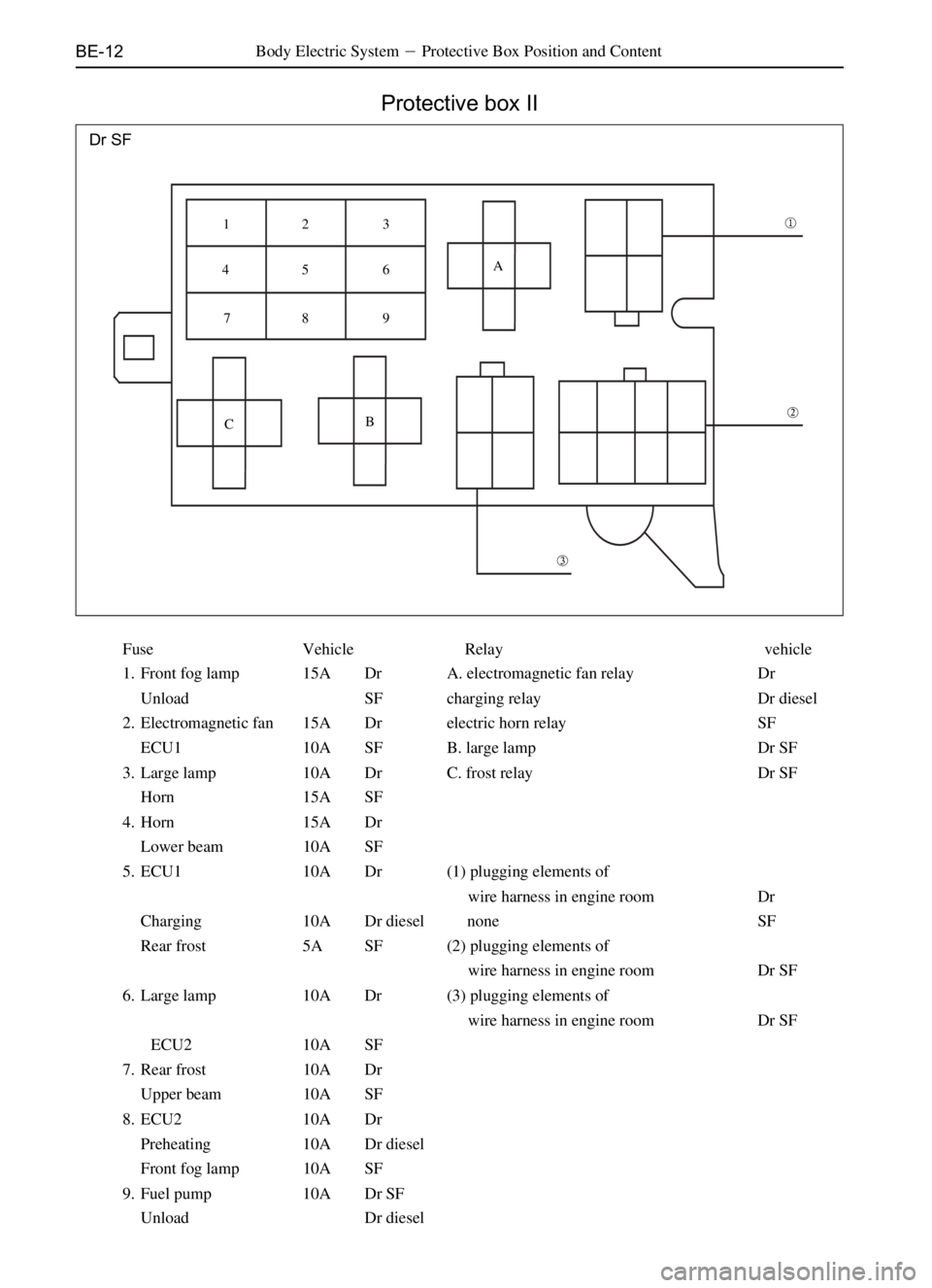
Protective box II
Body Electric System�Protective Box Position and Content
Dr SF
Fuse Vehicle Relay vehicle
1. Front fog lamp 15A Dr A. electromagnetic fan relay Dr
Unload SF charging relay Dr diesel
2. Electromagnetic fan 15A Dr electric horn relay SF
ECU1 10A SF B. large lamp Dr SF
3. Large lamp 10A Dr C. frost relay Dr SF
Horn 15A SF
4. Horn 15A Dr
Lower beam 10A SF
5. ECU1 10A Dr (1) plugging elements of
wire harness in engine room Dr
Charging 10A Dr diesel none SF
Rear frost 5A SF (2) plugging elements of
wire harness in engine room Dr SF
6. Large lamp 10A Dr (3) plugging elements of
wire harness in engine room Dr SF
ECU2 10A SF
7. Rear frost 10A Dr
Upper beam 10A SF
8. ECU2 10A Dr
Preheating 10A Dr diesel
Front fog lamp 10A SF
9. Fuel pump 10A Dr SF
Unload Dr diesel
�
�
� A
B
C 12 3
45 6
78 9
Page 291 of 484

Fuse Vehicle Relay Vehicle
1. Standby 10A SL SK A.electromagnetic fan relay SL SK
2. Standby 10A SL SK small")
BE-13Body Electric System�Protective Box Position and Content
Protective box II (continued)
Fuse Vehicle Relay Vehicle
1. Standby 10A SL SK A.electromagnetic fan relay SL SK
2. Standby 10A SL SK small lamp relay (SL diesel)
3. Standby 30A SL SK B.electric window relay SL SK
20A (SL diesel) cold start relay (SL diesel)
4. Rear fog lamp 10A SL SK C.frost relay SL SKLeft
large lamp 10A (SL diesel) charging relay) (SL diesel)
5. Front fog lamp 10A SL SK D.blower relay) SL SK
Right large lamp 10A (SL diesel) thermostatic relay (SL diesel)
6. Small lamp 10A SL SK E.small lamp relay SL SK
Air-conditioner 10A (SL diesel) heating relay (SL diesel)
7. Electric horn 10A SL SK F.large lamp relay SL SK
Warm air 20A (SL diesel) G.air-conditioner relay SL SK
8. Electric window 30A SL SK frost relay (SL diesel)
Unloa (SL diesel) H.rain-brusher intermissive relay SL SK
9. A/C 10A SL SK I.diod SL SK
Charging 10A (SL diesel)
10. Air blower 30A SL SK
Electric horn 10A (SL diesel)
11. Electronic fan 10A SL SK
Dual flasher 10A (SL diesel)
12. Right large lamp 10A SL SK
Unload (SL diesel)
13. Left large lamp 10A SL SK
Fog lamp 10A (SL diesel)
14. 60A fuse SL SK
15. 60A fuse SL SK
16. 30A fuse SL SK
17. 30A fuse SL SK
Unload SL diesel
123
H4567
14
15
GEFCD AB 8 9 10 11 12 13
SL SK
17
16
I
Page 292 of 484

3. Standby 30A SY SJ B. electric window relay SY SJ
4. Rear f")
BE-14
Fuse Vehicle Relay Vehicle
1. Standby 10A SY SJ A. electromagnetic fan relay SY SJ
2. Standby 10A SY SJ small lamp relay (SY diesel)
3. Standby 30A SY SJ B. electric window relay SY SJ
4. Rear fog lamp 10A SY SJ cold start relay (SY diesel)
Left large lamp 10A (SY diesel) air-conditioner relay SJ
5. Front fog lamp 10A SY SJ C. frost relay SY SJ
Right large lamp 10A (SY diesel) charging relay (SY diesel)
6. Small lamp 10A SY SJ D. blower relay SY SJ
Air-conditioner 10A (SY diesel) thermostatic relay (SY diesel)
7. Electric horn 10A SY SJ E. small lamp relay SY SJ
Warm air 20A (SY diesel) heating relay (SY diesel)
8. ECM 10A SY SJ rear defrost relay SJ
Unload (SY diesel) F. large lamp SY SJ
9. Fuel pump 10A SY SJ H. rain-brusher intermissive relay SY SJ
Charging 10A (SY DIESEL) I. diode SY SJ
10. Air blower 30A SY SJ
Electric horn 10A (SY diesel)
11. Electronic fan 10A SY SJ
Dual flasher 10A (SY diesel)
12. Right large lamp 10A SY SJ
Rear fog lamp 10A (SY diesel)
13. Left large lamp 10A SY SJ
Front fog lamp 10A (SY diesel)
14. 60A fuse SY SJ
15. 60A fuse SY SJ
16. 30A fuse SY SJ
17. 30A fuse SY SJ
Unload (SY diesel)
Protective box II (continued)
Body Electric System�Protective Box Position and Content
12 3 4
17
1614
15
IH
G
EF CD A
B 5 6 7 8 9 1011 1213
SY SJ
Page 310 of 484

BE-32Body Electric System�Combination Instrument
Combination instrument
Electric circuit diagram
��
�� ���� ��
��
��
��
^N ^NS _N _ N P
DraêaáÉëÉärear fog lamp indicating lamp
rear window/defroster indicating lamp
upper beam indicating lamp
front fog-lamp indicating lamp
A13�B3�
connected
with
negative
pole
A10
connected
with
positive
pole
A2
connected
with
negative
polewater
thermometer
tachometer
speedometerconnected with sensor
connected with revolution signal
connected with sensor anode
connected with sensor
fuel gauge
connected with sensor
braking liquid level indicating lamp
parking brake indicating lamp
safety airbag indicating lamp
low oil pressure indicating lamp
engine failure indicating lamp
four wheel drive indicating lamp
generator preheating indicating lamp
fuel alarming indicating lamp
accumulator charging indicating lamp
ABS failure indicating lamp
left turn indicating lamp
right turn indicating lamp
instrument interior
lighting lamp
liquid crystal back-light lamp
A1A16 B1 A5 A6A7 A8 A9 B6 B8 B9B10 B11A12 B4
A15
A14
A10
connected
with
positive
pole
A3
A4
B12
B13
B5
A13�B3�
connected
with
negative
pole
A10
connected
with
positive
pole
A2
connected
with
negative
pole
liquid crystal back-light lampinstrument interior
lighting lamp
rear fog lamp indicating lamp
upper beam indicating lamp
front fog-lamp indicating lamp
water
thermometer
tachometer
speedometer
fuel gaugeconnection with sensor
connected with revolution signal
connected with sensor anode
connected with sensor
connected with sensor
oil-water separation indicating lamp
safety belt indicating lamp
parking brake indicating lamp
braking liquid level indicating lamp
low oil pressure indicating lamp
engine failure indicating lamp
four wheel drive indicating lamp
generator preheating indicating lamp
fuel alarming indicating lamp
accumulator charging indicating lamp
ABS failure indicating lamp
left turn indicating lamp
right turn indicating lamp
A1 A16 B1
A5 A6 A7A8
A9 B6 B8
B9 B10
B11 A4A12 A14 A15B4
A10
connected
with
positive
pole
A3
B12
B13
B5
Page 311 of 484

SF
A3 connected
with negative pole
A1 connected
with positive pole
B8 connected
with negative
pole
B7connected
wi")
BE-33Body Electric System�Combination Instrument
Electric circuit diagram (continued)
SF
A3 connected
with negative pole
A1 connected
with positive pole
B8 connected
with negative
pole
B7connected
with positive
pole
A4 connecting
with lighting
switch
A6 connected
with negative
pole
pressure-regulating
potential deviceirect-current
power supply
5-9Vdrive power
supply
110VEL
luminous
plate
left turn indicating lamp
right turn indicating lamp
upper beam indicating lamp
rear fog lamp indicating lamp
rear window/defroster indicating lamp
front fog-lamp indicating lamp
water
thermometer
tachometer
connected with sensor
connected with revolution signal
speedometer
digital clock
fuel gaugeconnect to the cathode of sensor
connected with sensor anode
connected with sensor
connected with sensor
back door indicating lamp
parking brake indicating lamp
safety airbag indicating lamp
low oil pressure indicating lamp
engine failure indicating lamp
four wheel drive indicating lamp
generator preheating indicating lamp
fuel alarming indicating lamp
accumulator charging indicating lamp
ABS failure indicating lamp75�B9
B2 A15 B1 A9 B11 B10
A14 B4 B6 A12
B14 connected
with positive
pole
B7 connected
with positive
pole
A11 A5A7 B12B5 B13 A16A13 B16 B15
A2
1
2
3
4
5
6
7
8
9
10
11
12
13
14
15
16
In this drawing, A stands for the white plugging
elements, B for black plugging elements, they
use the same numerical order.
instrument
plugging element