2006 GREAT WALL HOVER transmission fluid
[x] Cancel search: transmission fluidPage 131 of 425
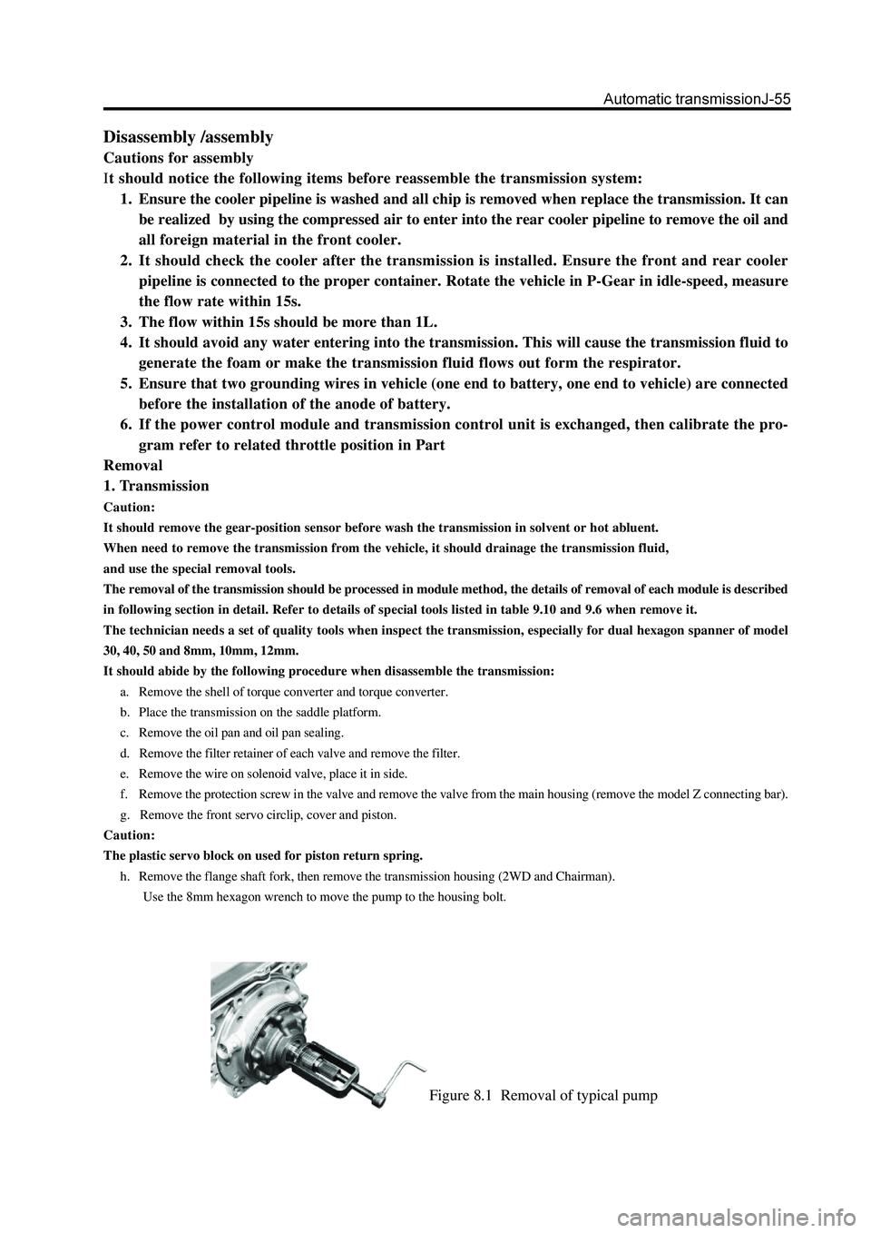
Figure 8.1 Removal of typical pump
Disassembly /assembly
Cautions for assembly
It should notice the following items before reassemble the transmission system:
1. Ensure the cooler pipeline is washed and all chip is removed when replace the transmission. It can
be realized by using the compressed air to enter into the rear cooler pipeline to remove the oil and
all foreign material in the front cooler.
2. It should check the cooler after the transmission is installed. Ensure the front and rear cooler
pipeline is connected to the proper container. Rotate the vehicle in P-Gear in idle-speed, measure
the flow rate within 15s.
3. The flow within 15s should be more than 1L.
4. It should avoid any water entering into the transmission. This will cause the transmission fluid to
generate the foam or make the transmission fluid flows out form the respirator.
5. Ensure that two grounding wires in vehicle (one end to battery, one end to vehicle) are connected
before the installation of the anode of battery.
6. If the power control module and transmission control unit is exchanged, then calibrate the pro-
gram refer to related throttle position in Part
Removal
1. Transmission
Caution:
It should remove the gear-position sensor before wash the transmission in solvent or hot abluent.
When need to remove the transmission from the vehicle, it should drainage the transmission fluid,
and use the special removal tools.
The removal of the transmission should be processed in module method, the details of removal of each module is described
in following section in detail. Refer to details of special tools listed in table 9.10 and 9.6 when remove it.
The technician needs a set of quality tools when inspect the transmission, especially for dual hexagon spanner of model
30, 40, 50 and 8mm, 10mm, 12mm.
It should abide by the following procedure when disassemble the transmission:
a. Remove the shell of torque converter and torque converter.
b. Place the transmission on the saddle platform.
c. Remove the oil pan and oil pan sealing.
d. Remove the filter retainer of each valve and remove the filter.
e. Remove the wire on solenoid valve, place it in side.
f. Remove the protection screw in the valve and remove the valve from the main housing (remove the model Z connecting bar).
g. Remove the front servo circlip, cover and piston.
Caution:
The plastic servo block on used for piston return spring.
h. Remove the flange shaft fork, then remove the transmission housing (2WD and Chairman).
Use the 8mm hexagon wrench to move the pump to the housing bolt.
Page 141 of 425

Figure 8.19 Position of thrust bearing and sealing pad
4. Rear servo assembly
Install the rear servo assembly (Refer to Figure 8.18), the procedure is shown as follows:
a. Check the servo piston O-ring and washer for damage.
b. Use the transmission fluid to lubricate the servo piston O-ring and install the O-ring on the piston groove.
c. Install the piston on the housing; ensure the O-ring is compressed to position, but do not excess.
d. Adjust the spring and piston sleeve; then install the rear servo brake bar on the sleeve.
Caution:
Do not coat the washer with the Vaseline.
e. Install the housing installed with washer on the case.
f. Provide the bolt with the Loctite567 sealant and install it; ensure the bolt is tightened according to the specification.
5. Planet carrier assembly and central support
The installation process of planet carrier assembly and central support is shown as follows:
a. Check the bracket and planet assembly for damage or abnormal and ensure all pinion rotates freely and the pinion axle end
floats in the allowable range; described as 9.2.
b. Install the one-way clutch fixing plate on the planet carrier and ensure the internal edge points to the downwardly. Check the
one-way clutch and brake accessory for damage; replace it according to the requirement.
c. Install the external race on the drum. Press sown the ring race to bottom of drum and install the fixing ring spring. Ensure the
ring spring is installed in the groove stably. Refer to Figure 8.20.
d. Install the one-way brake on the external race with the lip upwardly. Use the automatic transmission liquid to lubricate the
brake accessories. Refer to Figure 8.20.
Page 146 of 425
o. Maintain the horizontal position of cylinder , install the sleeve and clutch disk assembly on the cylinder; ensure the top of
washer and external hole of cylinder are in order until the sleeve can contact the C2 wave plate.
Caution:
For the C2 wave spring is compressed and the clutch disk can endure the weight of 19.6N. The dimension form the lower
side of C2 pressure disc to the gear selection steel plate is 1.4
1.8mm. if the clutch need to start the accuracy from the
top of pressure plate, then the accurate value should be the actual size of pressure plate plus 1.4
1.8mm.
p. Use the special tools to check the C4 clutch assembly. Refer to Figure 8.25.
Caution:
It should take out the clutch clearance assembly before immerse the assembly into the automatic transmission fluid
(ATF).
q. Use the gear selection plate to reach the correct specification. If need to install the new friction disk, it should remove the
clutch assembly and immerse the friction disk in the automatic transmission fluid for 5 minutes at least before the installation.
Reinstall the sleeve and clutch assembly and place it in the cylinder. Ensure the wave washer is arranged consisting with the
cylinder hole.
Install the clutch C2 disk in the cylinder according to the following procedure:
friction disk
steel disc
friction disk
steel disc
The steel disc transmission use the G32 model engine; the 5th friction disk should replace the steel disc (reference table 9.3).
steel disc (optional)
friction disk
steel disc (optional)
friction disk
Caution:
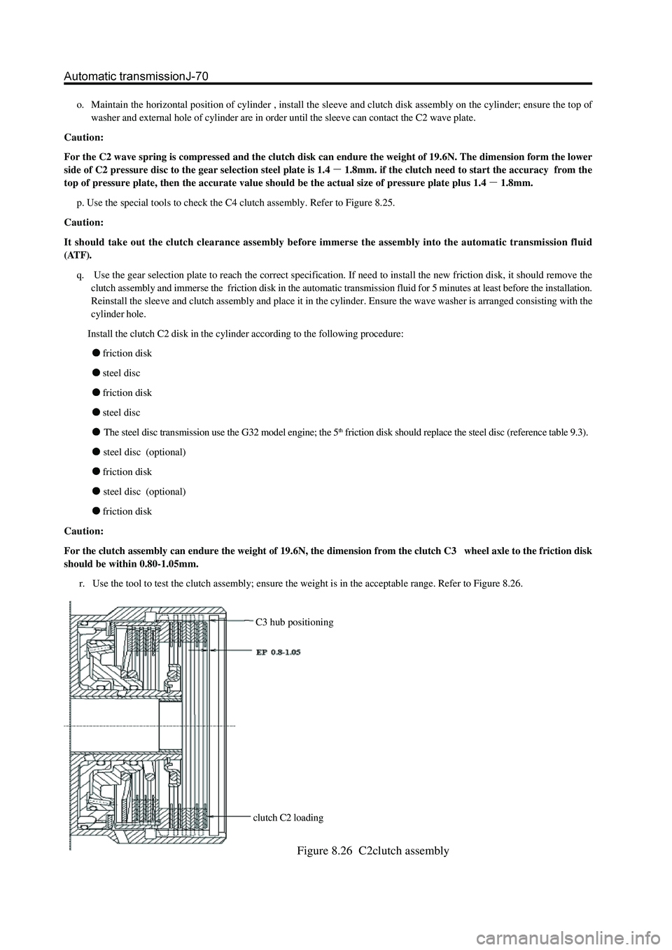
For the clutch assembly can endure the weight of 19.6N, the dimension from the clutch C3 wheel axle to the friction disk
should be within 0.80-1.05mm.
r. Use the tool to test the clutch assembly; ensure the weight is in the acceptable range. Refer to Figure 8.26.
C3 hub positioning
clutch C2 loading
Figure 8.26 C2clutch assembly
Page 147 of 425
v. Install the thrust disc on the cylinder internal wheel axle. Refer to Figure 8.24and 8.19.
w. Connect the C2 /clutch C4 wheel axle assembly in clutch C4 disc, install the clutch C2 disc. Install the C3 wheel axle and
reinforce it by ring spring; ensure the ring spring is installed in the groove fixedly. Please refer to Figure 8.24.
10. Clutch C3 and reverse central gear system
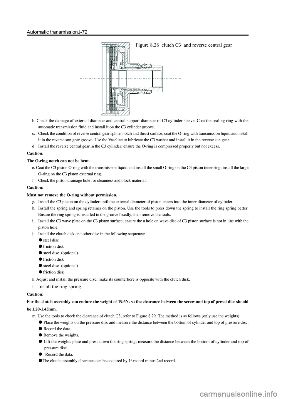
The assembly procedure of clutch C3 and reverse central gear assembly (refer to Figure 8.28) is shown as follows:
Check the cleanness of hole on cylinder. Caution:
It should take out the clutch clearance assembly before immerse the assembly into the automatic transmission fluid
(ATF).
s. Use the gear selection plate to reach the correct specification. It should remove the clutch assembly and immerse the friction
disk in the automatic transmission fluid for 5 minutes at least before the installation if install the new friction disks. Lubricate
and install the 3-4 one-way clutch and install the sleeve on the C2 wheel axle. Adjust the handle rear and install the nylon thrust
washer on the C4 wheel axle. Refer to Figure 8.27.
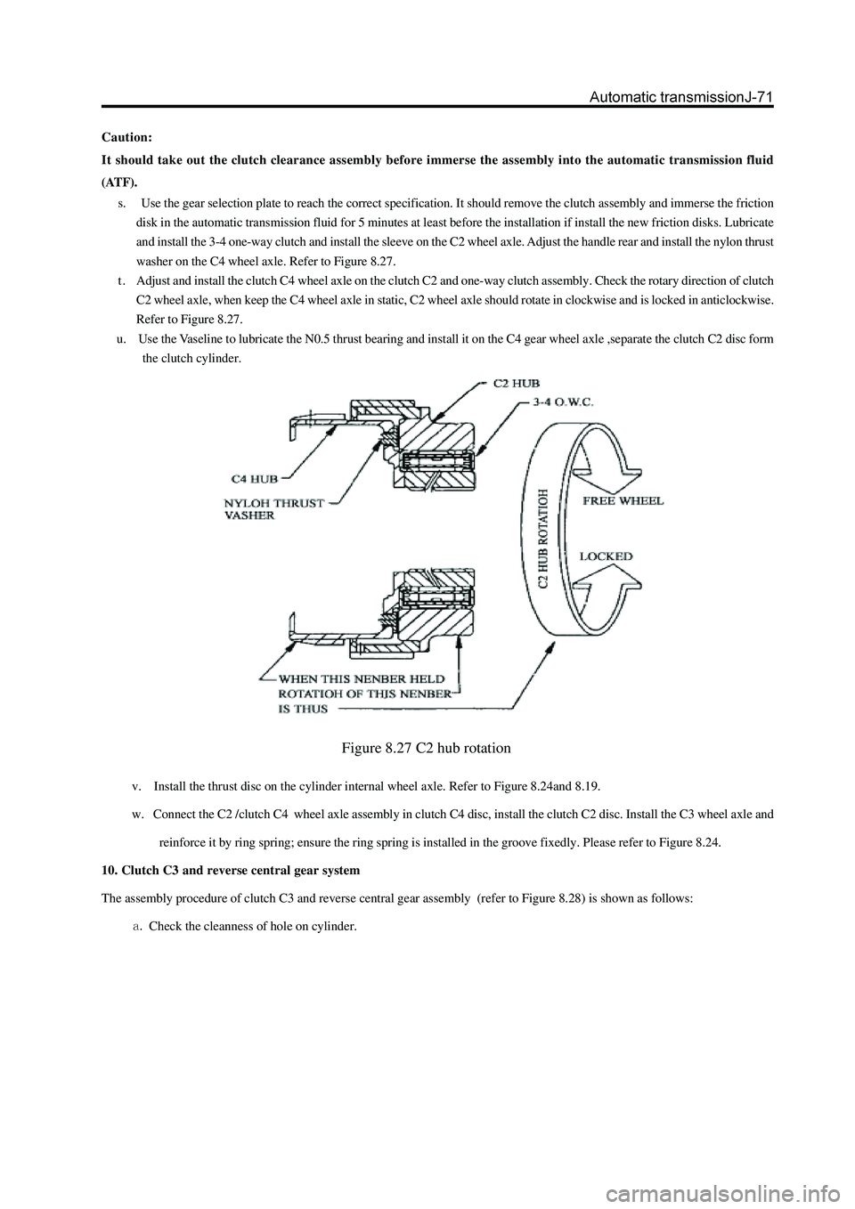
t . Adjust and install the clutch C4 wheel axle on the clutch C2 and one-way clutch assembly. Check the rotary direction of clutch
C2 wheel axle, when keep the C4 wheel axle in static, C2 wheel axle should rotate in clockwise and is locked in anticlockwise.
Refer to Figure 8.27.
u. Use the Vaseline to lubricate the N0.5 thrust bearing and install it on the C4 gear wheel axle ,separate the clutch C2 disc form
the clutch cylinder.
Figure 8.27 C2 hub rotation
Page 148 of 425
b. Check the damage of external diameter and central support diameter of C3 cylinder sleeve. Coat the sealing ring with the
automatic transmission fluid and install it on the C3 cylinder groove.
c. Check the condition of reverse central gear spline, notch and thrust surface; coat the O-ring with transmission liquid and install
it in the reverse sun gear groove. Use the Vaseline to lubricate the C3 washer and install it in the reverse sun gear.
d. Install the reverse central gear in the C3 cylinder; ensure the O-ring is compressed properly but not excess.
Caution:
The O-ring notch can not be bent.
e. Coat the C3 piston O-ring with the transmission liquid and install the small O-ring on the C3 piston inner ring; install the large
O-ring on the C3 piston external ring.
f. Check the piston drainage hole for cleanness and block material.
Caution:
Must not remove the O-ring without permission.
g. Install the C3 piston on the cylinder until the external diameter of piston enters into the inner diameter of cylinder.
h. Install the spring and spring retainer on the piston. Use the tools to press down the spring to install the ring spring better.
Ensure the ring spring is installed in the groove fixedly, then remove the tools.
i. Install the C3 wave plate on the C3 piston surface; ensure the a hole on wave disc of C3 piston surface is not in line with the
piston hole.
j. Install the clutch disk and other disc in the following sequence:
steel disc
friction disk
steel disc (optional)
friction disk
steel disc (optional)
friction disk
k. Adjust and install the pressure disc; make its counterbore is opposite with the clutch disk.
l. Install the ring spring.
Caution:
For the clutch assembly can endure the weight of 19.6N. so the clearance between the screw and top of preset disc should
be 1.20-1.45mm.
m. Use the tools to check the clearance of clutch C3, refer to Figure 8.29. The method is as follows (only use the weights):
Place the weights on the pressure disc and measure the distance between the bottom of cylinder and top of pressure disc.
Record the data.
Remove the weights.
Lift the weights plate and press down the ring spring; measure the distance between the bottom of cylinder and top of
pressure disc
Record the data.
The clutch assembly clearance can be acquired by 1st record minus 2nd record.
Figure 8.28 clutch C3 and reverse central gear
Page 150 of 425
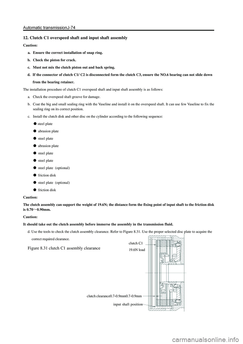
12. Clutch C1 overspeed shaft and input shaft assembly
Caution:
a. Ensure the correct installation of snap ring.
b. Check the piston for crack.
c. Must not mix the clutch piston out and back spring.
d. If the connector of clutch C1/ C2 is disconnected form the clutch C3, ensure the NO.6 bearing can not slide down
from the bearing retainer.
The installation procedure of clutch C1 overspeed shaft and input shaft assembly is as follows:
a. Check the overspeed shaft groove for damage.
b. Coat the big and small sealing ring with the Vaseline and install it on the overspeed shaft. It can use few Vaseline to fix the
sealing ring on its correct position.
c. Install the clutch disk and other disc on the cylinder according to the following sequence:
steel plate
abrasion plate
steel plate
abrasion plate
steel plate
steel plate
steel plate (optional)
friction disk
steel plate (optional)
friction disk
Caution:
The clutch assembly can support the weight of 19.6N; the distance form the fixing point of input shaft to the friction disk
is 0.70
0.90mm.
Caution:
It should take out the clutch assembly before immerse the assembly in the transmission fluid.
d. Use the tools to check the clutch assembly clearance. Refer to Figure 8.31. Use the proper selected disc plate to acquire the
correct required clearance.
Figure 8.31 clutch C1 assembly clearance
clutch C1
19.6N load
input shaft position
clutch clearance0.7-0.9mm0.7-0.9mm
Page 151 of 425
e. If need to install the new friction disk, please remove the clutch assembly and immerse the friction assembly into the
transmission fluid for 5 minutes at least before the installation.
f. Check whether the clutch C1 wheel axle is matched with the overspeed shaft. It should replace the wheel axle and wheel axle
assembly if loose.
g. Coat the small nylon thrust insulation plate with the Vaseline and installs it on the overspeed shaft. Refer to Figure 8.19.
h. It should be carefully when install the overspeed shaft on the C1 cylinder to avoid the damage of sealing ring.
i. Use the Vaseline to install the small copper C1 wheel axle thrust washer, shown as Figure 8.19.
j. Check the input shaft for problem. Install the input shaft on the cylinder and use the ring spring to install the wire safety of
input shaft and cylinder. Ensure the coil is in groove completely.
k. Use the petroleum jelly to install the gasket and place it on the input shaft.
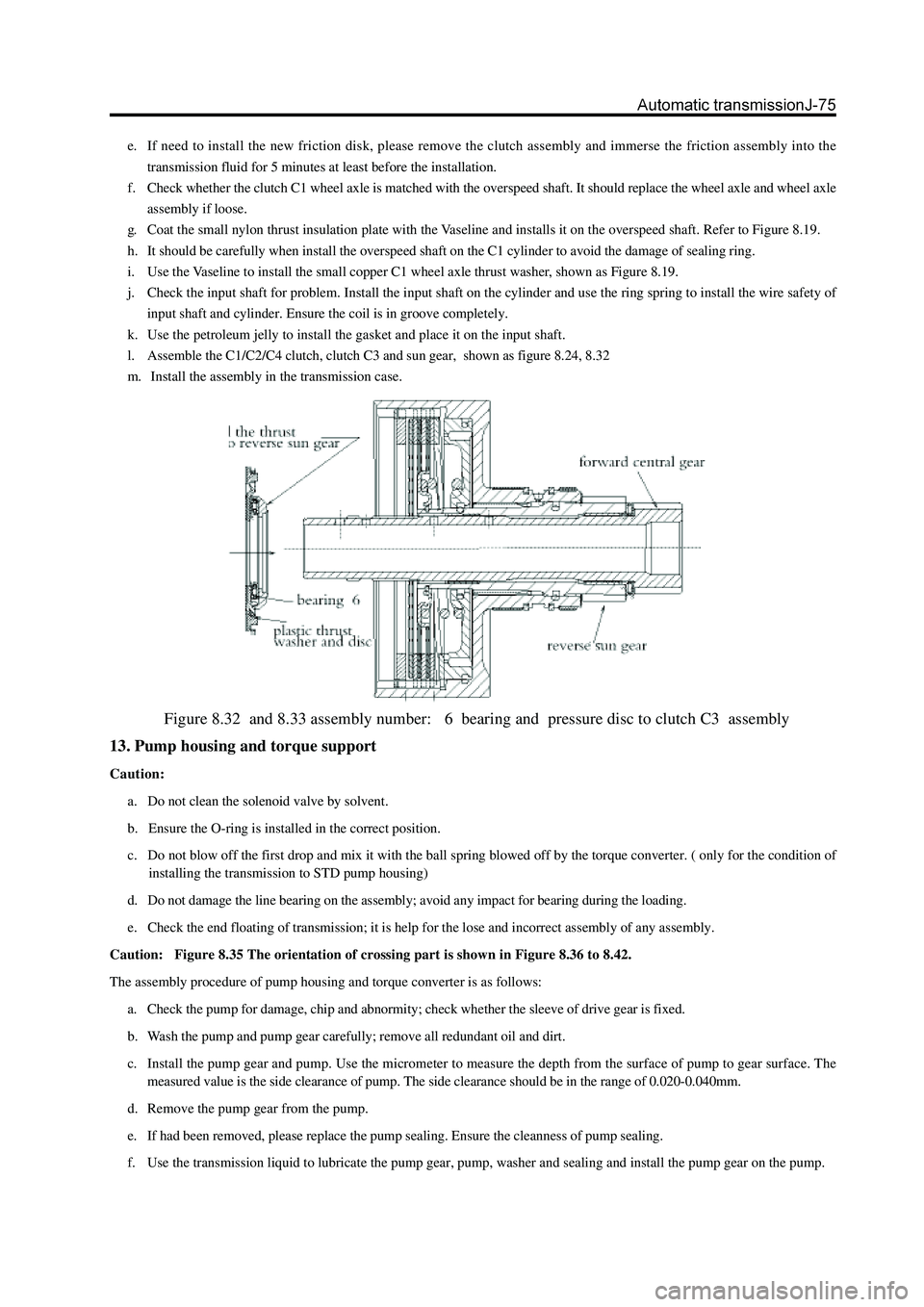
l. Assemble the C1/C2/C4 clutch, clutch C3 and sun gear, shown as figure 8.24, 8.32
m. Install the assembly in the transmission case.
Figure 8.32 and 8.33 assembly number: 6 bearing and pressure disc to clutch C3 assembly
13. Pump housing and torque support
Caution:
a. Do not clean the solenoid valve by solvent.
b. Ensure the O-ring is installed in the correct position.
c. Do not blow off the first drop and mix it with the ball spring blowed off by the torque converter. ( only for the condition of
installing the transmission to STD pump housing)
d. Do not damage the line bearing on the assembly; avoid any impact for bearing during the loading.
e. Check the end floating of transmission; it is help for the lose and incorrect assembly of any assembly.
Caution: Figure 8.35 The orientation of crossing part is shown in Figure 8.36 to 8.42.
The assembly procedure of pump housing and torque converter is as follows:
a. Check the pump for damage, chip and abnormity; check whether the sleeve of drive gear is fixed.
b. Wash the pump and pump gear carefully; remove all redundant oil and dirt.
c. Install the pump gear and pump. Use the micrometer to measure the depth from the surface of pump to gear surface. The
measured value is the side clearance of pump. The side clearance should be in the range of 0.020-0.040mm.
d. Remove the pump gear from the pump.
e. If had been removed, please replace the pump sealing. Ensure the cleanness of pump sealing.
f. Use the transmission liquid to lubricate the pump gear, pump, washer and sealing and install the pump gear on the pump.
Page 418 of 425

Appendix B-12
Non-metal materials consumption table
Name Brand, specification and
technical condition Utility Measuring
unit Suitable Note
Silicon oil Transmission lever. Three-hole
rubber block Kg Suitable
Thread block
sealing agent 1271 Short, longitudinal front fixed
bolt, hub cap bolt, transmission
lever bolt, carriage fixing L Suitable
Silicone rubber
surface sealing
agent 1596 (super gray) Installing ring flange L Suitable
Anti-freeze
liquid vinyl-EG --35℃
antifreeze liquid Radiator and co-tank - Kg 7
Molybdenum
disulfide
pressed
lithium base
grease 3# Twisted bar spline, speed shaft L Suitable
Glass base
coat er 5001TF Glass base coat m 0.03
Butyl tape 6×2×700 Air-filtering suction tube, door
seal film L Suitable
Attraction
steering fluid DEXRON3 (ATF-3) Steering fuel cup assembly L 1
Clutch oil DOT4 Clutch master cylinder L 0.15
Brake fluid DOT4 Vacuum assist fluid reservoir L 0.525
Auto gear oil GL-4 75W/90 Transmission L 2.2 For the exported
vehicle for
extremely cold
areas
Auto gear oil GL-4 75W/90 Transfer case L 2.7 For the exported
vehicle for
extremely cold
areas
Auto gear oil GL-4 80W/90 Transmission L 1.4
Auto gear oil GL-4 80W/90 Transfer case L 2.5
Auto gear oil GL-5 75W/90 Rear axle L 2.9 For the exported
vehicle for
extremely cold
areas
2.9L=5.14PTS
Auto gear oil GL-5 80W/90 Rear axle L 2.9 2.9L=5.14PTS