2006 GREAT WALL HOVER steering
[x] Cancel search: steeringPage 129 of 425

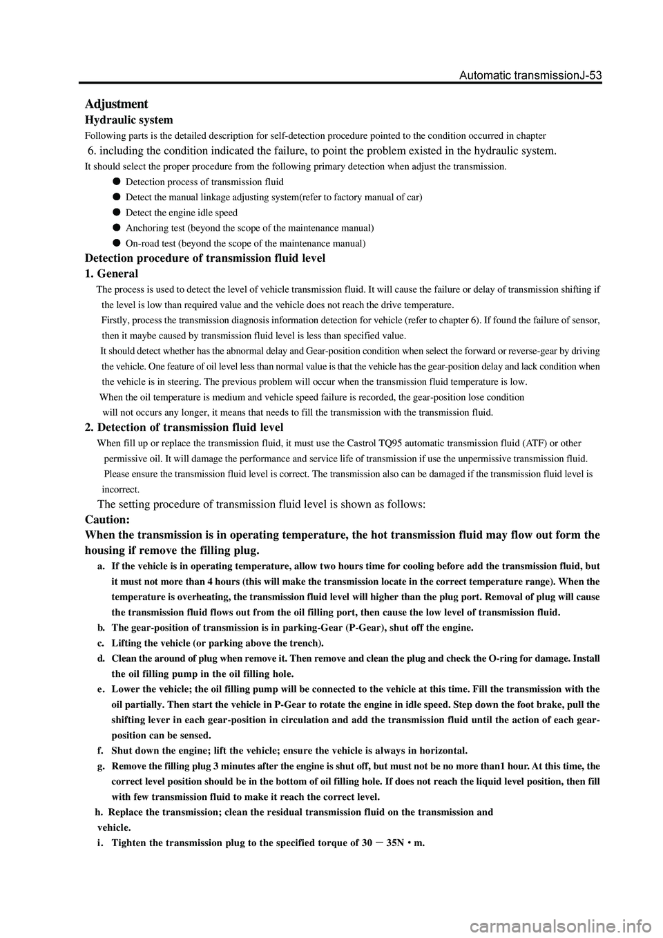
Adjustment
Hydraulic system
Following parts is the detailed description for self-detection procedure pointed to the condition occurred in chapter
6. including the condition indicated the failure, to point the problem existed in the hydraulic system.
It should select the proper procedure from the following primary detection when adjust the transmission.
Detection process of transmission fluid
Detect the manual linkage adjusting system(refer to factory manual of car)
Detect the engine idle speed
Anchoring test (beyond the scope of the maintenance manual)
On-road test (beyond the scope of the maintenance manual)
Detection procedure of transmission fluid level
1. General
The process is used to detect the level of vehicle transmission fluid. It will cause the failure or delay of transmission shifting if
the level is low than required value and the vehicle does not reach the drive temperature.
Firstly, process the transmission diagnosis information detection for vehicle (refer to chapter 6). If found the failure of sensor,
then it maybe caused by transmission fluid level is less than specified value.
It should detect whether has the abnormal delay and Gear-position condition when select the forward or reverse-gear by driving
the vehicle. One feature of oil level less than normal value is that the vehicle has the gear-position delay and lack condition when
the vehicle is in steering. The previous problem will occur when the transmission fluid temperature is low.
When the oil temperature is medium and vehicle speed failure is recorded, the gear-position lose condition
will not occurs any longer, it means that needs to fill the transmission with the transmission fluid.
2. Detection of transmission fluid level
When fill up or replace the transmission fluid, it must use the Castrol TQ95 automatic transmission fluid (ATF) or other
permissive oil. It will damage the performance and service life of transmission if use the unpermissive transmission fluid.
Please ensure the transmission fluid level is correct. The transmission also can be damaged if the transmission fluid level is
incorrect.
The setting procedure of transmission fluid level is shown as follows:
Caution:
When the transmission is in operating temperature, the hot transmission fluid may flow out form the
housing if remove the filling plug.
a. If the vehicle is in operating temperature, allow two hours time for cooling before add the transmission fluid, but
it must not more than 4 hours (this will make the transmission locate in the correct temperature range). When the
temperature is overheating, the transmission fluid level will higher than the plug port. Removal of plug will cause
the transmission fluid flows out from the oil filling port, then cause the low level of transmission fluid.
b. The gear-position of transmission is in parking-Gear (P-Gear), shut off the engine.
c. Lifting the vehicle (or parking above the trench).
d. Clean the around of plug when remove it. Then remove and clean the plug and check the O-ring for damage. Install
the oil filling pump in the oil filling hole.
e. Lower the vehicle; the oil filling pump will be connected to the vehicle at this time. Fill the transmission with the
oil partially. Then start the vehicle in P-Gear to rotate the engine in idle speed. Step down the foot brake, pull the
shifting lever in each gear-position in circulation and add the transmission fluid until the action of each gear-
position can be sensed.
f. Shut down the engine; lift the vehicle; ensure the vehicle is always in horizontal.
g. Remove the filling plug 3 minutes after the engine is shut off, but must not be no more than1 hour. At this time, the
correct level position should be in the bottom of oil filling hole. If does not reach the liquid level position, then fill
with few transmission fluid to make it reach the correct level.
h. Replace the transmission; clean the residual transmission fluid on the transmission and
vehicle.
i. Tighten the transmission plug to the specified torque of 30
35Nm.
Page 160 of 425

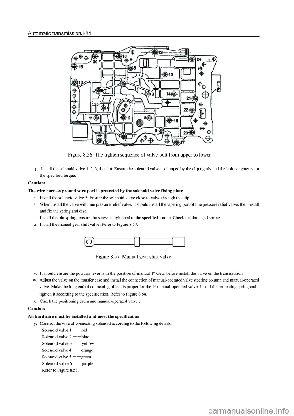
Figure 8.56 The tighten sequence of valve bolt from upper to lower
q. Install the solenoid valve 1, 2, 3, 4 and 6. Ensure the solenoid valve is clamped by the clip tightly and the bolt is tightened to
the specified torque.
Caution:
The wire harness ground wire port is protected by the solenoid valve fixing plate
r. Install the solenoid valve 5. Ensure the solenoid valve close to valve through the clip.
s. When install the valve with line pressure relief valve, it should install the tapering port of line pressure relief valve, then install
and fix the spring and disc.
t . Install the pin spring; ensure the screw is tightened to the specified torque. Check the damaged spring.
u. Install the manual gear shift valve .Refer to Figure 8.57.
Figure 8.57 Manual gear shift valve
v. It should ensure the position lever is in the position of manual 1st-Gear before install the valve on the transmission.
w. Adjust the valve on the transfer case and install the connection of manual-operated valve steering column and manual-operated
valve. Make the long end of connecting object is proper for the 1
st manual-operated valve. Install the protecting spring and
tighten it according to the specification. Refer to Figure 8.58.
x. Check the positioning drum and manual-operated valve .
Caution:
All hardware must be installed and meet the specification.
y . Connect the wire of connecting solenoid according to the following details:
Solenoid valve 1
red
Solenoid valve 2
blue
Solenoid valve 3
yellow
Solenoid valve 4
orange
Solenoid valve 5
green
Solenoid valve 6
purple
Refer to Figure 8.58.
Page 174 of 425

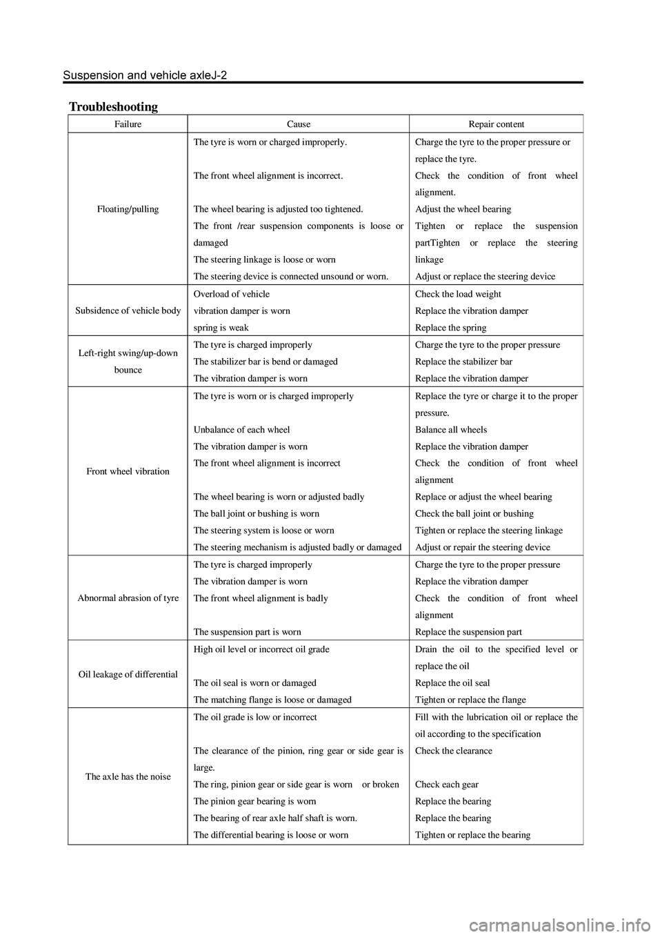
Troubleshooting
Failure Cause Repair cont ent
Floating/pulling The t yre is worn or charged improperly.
The front wheel alignment is incorrect.
The wheel bearing is adjusted too tightened.
The front /rear suspension components is loose or
damaged
The steering linkage is loose or worn
The steering device is connect ed unsound or worn. Charge the t yre to the prop er pressur e or
repla ce the t yre.
Check the condition of front wheel
alignment.
Adjust the wheel bearing
Tighten or replace the suspension
partTighten or replace the steering
linkage
Adjust or replace the steering device
Subsidence of vehicle body Overload of vehicle
vibration damper is worn
spring is weak Check the load weight
Replace the vibration damper
Replace the spring
Left-right swing/up-down
bounce The t yre is charged improperly
The stabilizer bar is bend or damaged
The vibration damper is worn Charge the t yre to the prop er pressur e
Replace the stabilizer bar
Replace the vibration damper
Front wheel vibration The t yre is worn or is charged improperly
Unbalance of each wheel
The vibration damper is worn
The front wheel alignment is incorrect
The wheel bearing is worn or adjusted badly
The ball joint or bushing is worn
The steering system is loose or worn
The steering mechanism is adjusted badly or damaged Repla ce the t yr e or char ge it to the prop er
pressure.
Balance all wheels
Replace the vibration damper
Check the condition of front wheel
alignment
Replace or adjust the wheel bearing
Check the ball joint or bushing
Tighten or replace the steering linkage
Adjust or repair the steering device
Abnormal abrasion of tyre The t yre is charged improperly
The vibration damper is worn
The front wheel alignment is badly
The suspension part is worn Charge the t yre to the prop er pressur e
Replace the vibration damper
Check the condition of front wheel
alignment
Replace the suspension part
Oil leakage of differential High oil level or incorrect oil grade
The oil seal is worn or damaged
The matching flange is loose or damaged Drain the oil to the specified level or
repla ce the oil
Replace the oil seal
Tighten or replace the flange
The axle has the nois e The oil grade is low or incorrect
The clearance of the pinion, ring gear or side gear is
large.
The ring, pinion gear or side gear is worn or broken
The pinion gear bearing is worn
The b earing of rear axle half shaft is worn.
The differential b earing is loos e or worn Fill with the lubrication oil or replace the
oil according to the specification
Check the clearance
Check each gear
Replace the bearing
Replace the bearing
Tighten or replace the bearing
Page 175 of 425

Front wheel alignment
1. Process the following inspection and eliminate
all problems
a. Check the wear condition of tyre and proper inflation.
Tyre inflation pressure: 230kPa
b. Check the wheel bearing of front wheel for loose.
c. Check the front suspension for loose.
d. Check the steering drive device for loose.
e. Process the standard elastic test; check thefrontvibration damper
for normal operation.
3. Install the 4-Wheel alignment instrument
Processed according to the detailed description of equipment
manufacturer.
4. Adjust the wheel angle
Remove the cover of spacing bolt of steering knuckle; check the internal
wheel’s steering angle A.
Internal wheel’s steering angle:
32
Caution: The wheel should not touch the brake hose of car body
when the steering wheel is rotated to limit.
2. Adjust the height of car
A:Adjust the height of car to the standard value for theconvenience of
processing the front wheel alignmentinspection.
B: Front fixed bolt of lower suspension arm
The standard no-load height is: the center of front fixed boltof lower
suspension arm is 295
1mm away form theground.
Page 179 of 425

Front hub and steering knuckle (2WD)
stabilizer bar
connecting rod
of stabilizer bar
flat shim
disk shim
fill block
shim
fill block
disk shim
absorber
bearing
hub cap
brake cover
spring shim
split pin
lower suspension arm
split pin
upper suspension arm
spring shimbrake caliper assembly
steering knuckle
tight nut
lock washer
screw
oil seal
bearing
hub and brake disc flat shim
N
m: specified torque
Used component which can not be used any more
precoated component
Page 182 of 425

2. Place in the bearing inner race; use the fill the gap
between the inner and outer race of the bearing up
with the HP-R grease.grease
grease
3. Install the inner bearing and oil seal
a. Place the inner bearing in the hub.
b. Use the special tools to knock the new oil seal into the hub.
c. Coat the oil seal lip with HP-R grease.
4. Install the hub on the steering knuckle
a. Install the hub on the steering knuckle.
b. Install the external bearing.
diagram of spe-
cial tools
special tools
5. Adjust the pre-applied load
a. Use the special tools to screw on the locknut to specified torque.
Tightening force: 80-100N
m
b. Rotate the hub to right and left 1/3
1/4 round respectively.
c. Screw off the nut until the nut can be loosed by hand.
d. Use the special tools to retighten the lock nut.
Tightening force: 28N
m
e. Use the spring tension meter to check the pre-applied load.
Pre-applied load (for starting): 28-56N
diagram of spe-
cial tools
special tools
Page 183 of 425

Remarks: If the screw installation hole on the lock washer can not
align with the screw hole on the lock nut, then it can remove the lock
washer and adjust he lock nut slightly (rotate in the direction of
Min. adjusting range ); then install the lock washer.
7. Recheck the pre-applied load
Use the spring tension meter to recheck the pre-applied load.
Pre-applied load (for starting): 28-56N
If the pre-applied load does not meet the specified value, it must remove
the lock washer and adjust it by the adjusting nut.
8. Install the hub cap
a. Coat the silicon rubber surface sealant on the matching surface of
hub and hub cap.
b. Coat the screw of the inner hexagon bolt with the screw lock sealant.
c. Use the inner hexagon bolt to fix the hub cap and ring flange on the
hub; tighten the bolt to the specified torque.
Tightening force: 45
5Nm
9. Install the disc brake
Install the disc brake on the steering knuckle and tighten the bolt to the
specified torque.
Tightening force: 140
10Nm
Page 184 of 425

Steering knuckle
Disassembly of steering knuckle
1. Remove the disc brake and front hub
(Refer to section “Front Hub”)
2. Remove the brake cover
special tools
special tools
special tools
3. Disconnect the steering cross rod from the steering
knuckle arm
a. Remove the split pin and nut on the ball pin.
4. Disconnect the connecting rod of stabilizer bar from
lower arm
Use the inner hexagon spanner to fix the ball pin; remove the self-
locking nut.
5. Remove the steering knuckle
a. Remove the split pin and nut on the upper ball pin
b. Use the special tools to disconnect the steering knuckle from the
upper ball pin.
c. Remove the split pin and nut on the lower ball pin.
d. Use the special tools to disconnect the steering knuckle from
the upper ball pin.
e. Remove the steering knuckle.