Page 175 of 425

Front wheel alignment
1. Process the following inspection and eliminate
all problems
a. Check the wear condition of tyre and proper inflation.
Tyre inflation pressure: 230kPa
b. Check the wheel bearing of front wheel for loose.
c. Check the front suspension for loose.
d. Check the steering drive device for loose.
e. Process the standard elastic test; check thefrontvibration damper
for normal operation.
3. Install the 4-Wheel alignment instrument
Processed according to the detailed description of equipment
manufacturer.
4. Adjust the wheel angle
Remove the cover of spacing bolt of steering knuckle; check the internal
wheel’s steering angle A.
Internal wheel’s steering angle:
32
Caution: The wheel should not touch the brake hose of car body
when the steering wheel is rotated to limit.
2. Adjust the height of car
A:Adjust the height of car to the standard value for theconvenience of
processing the front wheel alignmentinspection.
B: Front fixed bolt of lower suspension arm
The standard no-load height is: the center of front fixed boltof lower
suspension arm is 295
1mm away form theground.
Page 191 of 425
d. Tighten the adjusting bolt to make the extension length of the bolt
equal to the length before remove.
2. For new torsion bar spring
a. Remove the wheel.
b. Coat thin grease on the spline of the torsion bar spring.
c. Install the torsion bar spring on the torsion bar base.
d. Lower the lower arm to the lower limitation position; install the
adjusting arm in the torsion bar spring with the angle that the
adjusting bolt just can be screwed on the upper adjusting block.
e. Tighten the adjusting bolt to the specified torque.
Nut tightening limitation: A is about 30-35mm; if A>
35mm, then it is adjusted through height of adjusting arm.
f. Install the wheel; remove the bracket; bounce the vehicle for
several times to make the suspension enters into the stable
status.
g. Rotate the adjusting bolt and adjust the ground clearance of
chassis (Refer to 4-Wheel Alignment).
Page 214 of 425
d. Tighten the adjusting bolt and make the extension length of the
bolt equal to the value before disassembly.
2. For new torsion bar spring
a. Remove the wheel.
b. Coat the spline of torsion bar spring with thin grease.
c. Install the torsion bar spring on the torsion bar base.
d. Lower the lower arm to the lower limitation position; install
the adjusting arm in the torsion bar spring with the angle that
the adjusting bolt just can be screwed on the upper adjusting
block.
Remarks: It can repeat for several times until proper when
adjust the angle.
e. Tighten the adjusting bolt to the specified torque.
Nut tightening limitation: A is about 20-35mm; if A>35mm,
then it is adjusted through height of adjusting arm.
f. Install the wheel; remove the bracket; bounce the vehicle for
several times to make the suspension enters into the stable
status.
g. Rotate the adjusting bolt and adjust the ground clearance of
chassis (Refer to 4-Wheel Alignment).
Page 285 of 425

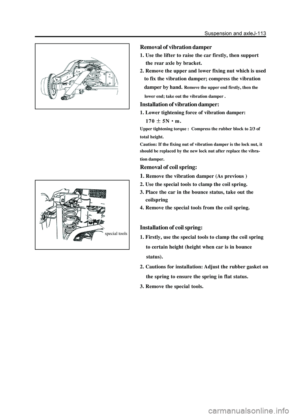
Removal of vibration damper
1. Use the lifter to raise the car firstly, then support
the rear axle by bracket.
2. Remove the upper and lower fixing nut which is used
to fix the vibration damper; compress the vibration
damper by hand.
Remove the upper end firstly, then the
lower end; take out the vibration damper .
Installation of vibration damper:
1. Lower tightening force of vibration damper:
170
5Nm.
Upper tightening torque : Compress the rubber block to 2/3 of
total height.
Caution: If the fixing nut of vibration damper is the lock nut, it
should be replaced by the new lock nut after replace the vibra-
tion damper.
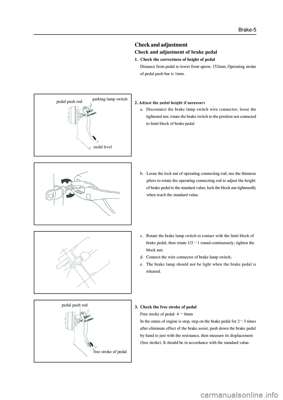
Removal of coil spring:
1
. Remove the vibration damper (As previous )
2. Use the special tools to clamp the coil spring.
3. Place the car in the bounce status, take out the
coilspring
4. Remove the special tools from the coil spring.
Installation of coil spring:
1. Firstly, use the special tools to clamp the coil spring
to certain height (height when car is in bounce
status).
2. Cautions for installation: Adjust the rubber gasket on
the spring to ensure the spring in flat status.
3. Remove the special tools.special tools
Page 291 of 425

Brake-5
Check and adjustment
Check and adjustment of brake pedal
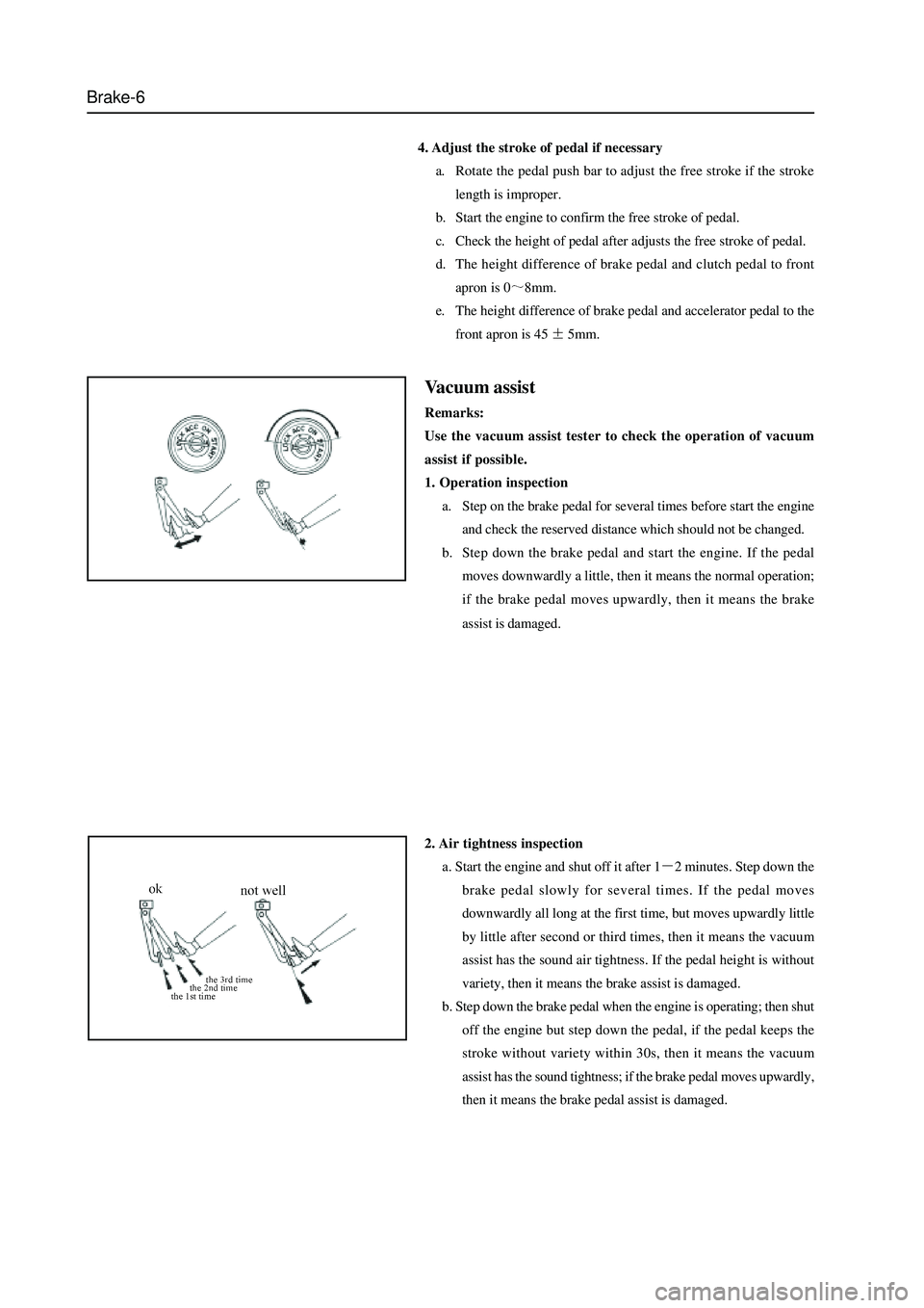
1. Check the correctness of height of pedal
Distance from pedal to lower front apron: 152mm, Operating stroke
of pedal push bar is 1mm.
a. Disconnect the brake lamp switch wire connector; loose the
tightened nut; rotate the brake switch to the position not contacted
to limit block of brake pedal
b. Loose the lock nut of operating connecting rod; use the thinnose
pliers to rotate the operating connecting rod to adjust the height
of brake pedal to the standard value; lock the block nut tightenedly
when reach the standard value.
c. Rotate the brake lamp switch to contact with the limit block of
brake pedal; then rotate 1/2
1 round continuously; tighten the
block nut;
d. Connect the wire connector of brake lamp switch;
e. The brake lamp should not be light when the brake pedal is
released.
3. Check the free stroke of pedal
Free stroke of pedal: 4
6mm
In the status of engine is stop, step on the brake pedal for 2
3 times
after eliminate effect of the brake assist, push down the brake pedal
by hand to just with the resistance, then measure its displacement
(free stroke). It should be in accordance with the standard value.
pedal push rodparking lamp switch
free stroke of pedal pedal push rod
Page 292 of 425

Brake-6
4. Adjust the stroke of pedal if necessary
a. Rotate the pedal push bar to adjust the free stroke if the stroke
length is improper.
b. Start the engine to confirm the free stroke of pedal.
c. Check the height of pedal after adjusts the free stroke of pedal.
d. The height difference of brake pedal and clutch pedal to front
apron is 0
8mm.
e. The height difference of brake pedal and accelerator pedal to the
front apron is 45
5mm.
Vacuum assist
Remarks:
Use the vacuum assist tester to check the operation of vacuum
assist if possible.
1. Operation inspection
a. Step on the brake pedal for several times before start the engine
and check the reserved distance which should not be changed.
b. Step down the brake pedal and start the engine. If the pedal
moves downwardly a little, then it means the normal operation;
if the brake pedal moves upwardly, then it means the brake
assist is damaged.
2. Air tightness inspection
a. Start the engine and shut off it after 1
2 minutes. Step down the
brake pedal slowly for several times. If the pedal moves
downwardly all long at the first time, but moves upwardly little
by little after second or third times, then it means the vacuum
assist has the sound air tightness. If the pedal height is without
variety, then it means the brake assist is damaged.
b. Step down the brake pedal when the engine is operating; then shut
off the engine but step down the pedal, if the pedal keeps the
stroke without variety within 30s, then it means the vacuum
assist has the sound tightness; if the brake pedal moves upwardly,
then it means the brake pedal assist is damaged.
Page 414 of 425

Appendix A-8
front windshield glass
Apply washer on the front windshield
glass-sticking regionEvenly apply it on the sticking region with the width of about
25mm and completely volatilize it.Viewing confirmation
Viewing confirmation Apply base-coater on the front
windshield glass-sticking regionShake the base-coater to be sufficiently even followed by the
even application on the sticking region with the width of about
20mm and dry it for 2-15 minutes
Apply washer on front windshield
glassWash the glass frame with the width of about 25mm,
instantly clean it and volatilize the washer completely.
Apply adhesive on front windshield
glassShake the glass base-coater to be sufficiently even followed
by the even application on the glass frame with the width of
about 20 and dry it for 2-15 minutes Apply base-coater on front
windshield glass
Vertically apply the glass adhesive on the glass frame and
make it even and continuous. Height: 18mm, width: 12mm
Front windshield glass fixing
Instantly install and fix the glass after the glass adhesive
application. Set the left and right clearance between front
windshield glass and the glass frame to be 12mmViewing confirmation
Viewing confirmation
Viewing confirmation
Viewing confirmation
Wash, base-coat and stick according to the corresponding positions showed by the broken line in the Figure
Page 415 of 425

Appendix A-9
Viewing confirmation
backup door
backup door glass
Wash, base-coat and stick according to the corresponding positions showed
by the broken line in the Figure
Apply washer on the glass-sticking
region of the backup doorViewing confirmation
Viewing confirmation
Shake the glass base-coater to be sufficiently even followed
by the even application on the glass frame with the width of
about 20 and dry it for 2-15 minutesViewing confirmation
Viewing confirmation
Evenly apply it on the sticking region with the width of about
25mm and volatilize it completely.
Shake the base-coater to be sufficiently even followed by the
even application on the sticking region with the width of
about 20mm and dry it for 2-15 minutes
Wash the glass frame with the width of about 25mm and
volatilize the washer Apply base-coater on the glass-
sticking region of the backup door
Apply washer on the backup door
glass frame
Apply base-coater on the backup
door glass frame
Apply adhesive on the backup door
glass frame
Backup door glass fixingInstantly install and fix the glass after the glass adhesive
application Vertically apply the glass adhesive on the glass frame and make
it even, continuous. Height: 12mm, width: 8mm
Viewing/handle
confirmation