Page 93 of 484
TF-27Transfer Box�Washing, Checking, Up-Keeping and Exchanging (Checking)
(h) Acceptable contact area deflecting to the tooth top.
(i) Unacceptable contact area deflecting to the tooth top,
which must be changed.
(j) Acceptable contact area deflecting to tooth root.
(k) Unacceptable contact area deflecting to tooth root, which
must be changed.
4. Key tooth inspection
Check the broken or peeled spline teeth. The spline teeth may,
if only small part is peeled off, be repaired in the same way as
that for the gear teeth, and can be reused. In case the spline
tooth is broken, the spline must be abandoned. The contact
type of spline is not the same as that for gear; however, spline
that shows step sliding must be abandoned.
Page 94 of 484

Maintenance or Change of Gear or Chain
Sprocket Gear
1. Maintenance principle
(a)")
TF-28Transfer Box�Washing, Checking, Up-Keeping and Exchanging (Maintenance or Change of Gear or Chain Sprocket Gear)
Maintenance or Change of Gear or Chain
Sprocket Gear
1. Maintenance principle
(a) Conduct the maintenance for the partial, small peel off
with the suitable manual high-speed grinding tool.
(b) Do not clear away the metal as can as possible when
grinding the matrix metal.
(c) All pointed angles and sides must be repaired as the slip-
pery contour line. Because the pointed angle or edges
may be peeled off again or developed into crack.
(d) Clear away the burr with the suitable grinding stone. Take
notice not to damage the matrix when clearing away the
projecting materials, and
(e) When substituting the non-repaired parts (such as
bearing), if the part is doubted in its re-application
capability, it must be changed.
2. Cases for gear or chain sprocket maintenance or substi-
tuting
(a) The gear, being peeled off at the two sides of tooth top in
contact face, may be repaired for reuse.
(b) The gear, being peeled off at the central tooth top of
contact face, may be repaired for reuse.
(c) The gear, being peeled off at one side of the non-contact
face, may be repaired for reuse.
Page 95 of 484
TF-29Transfer Box�Washing, Checking, Up-Keeping and Exchanging (Maintenance or Change of Gear or Chain Sprocket Gear)
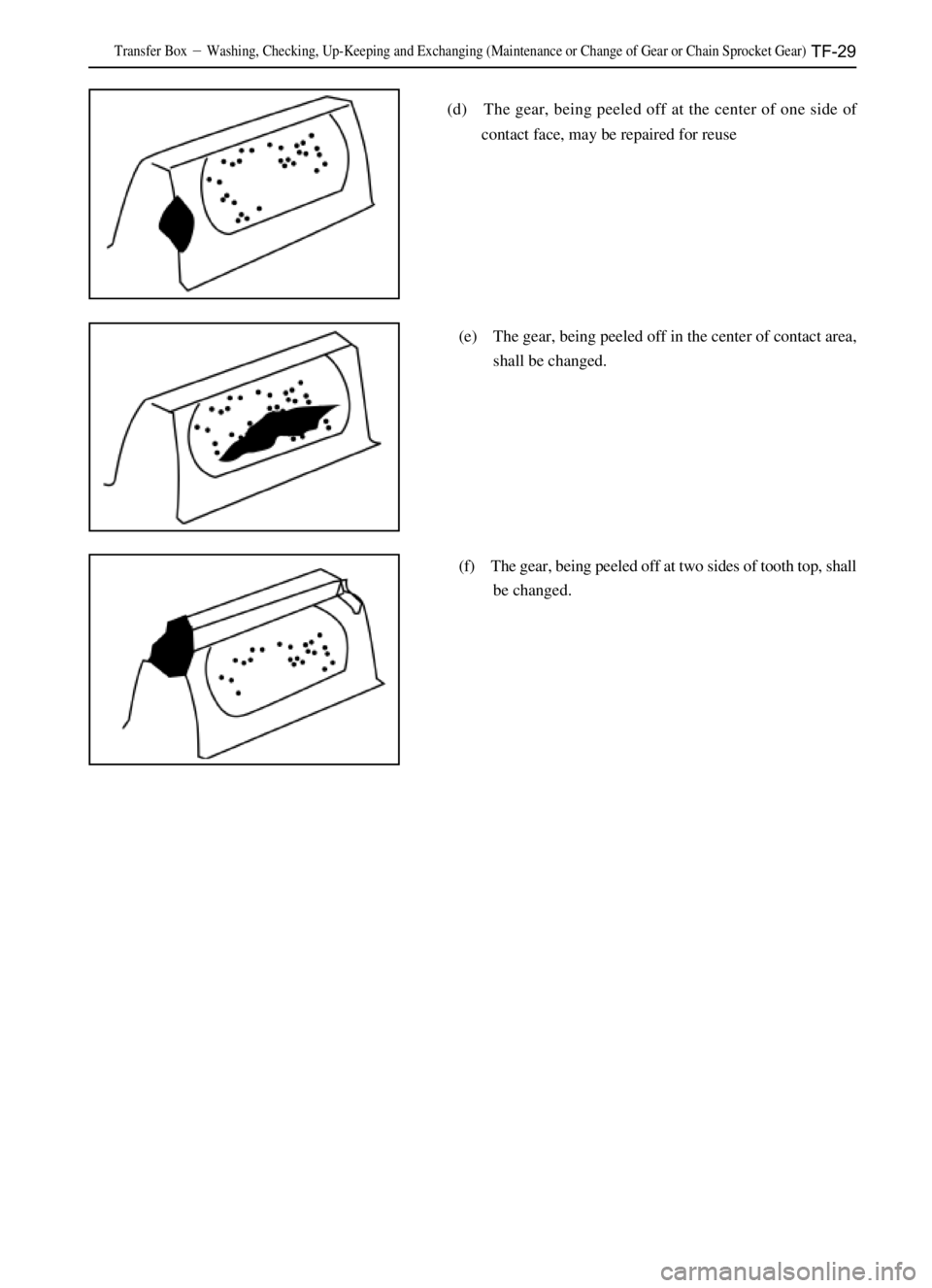
(d) The gear, being peeled off at the center of one side of
contact face, may be repaired for reuse
(e) The gear, being peeled off in the center of contact area,
shall be changed.
(f) The gear, being peeled off at two sides of tooth top, shall
be changed.
Page 113 of 484

SA-2
Troubleshooting
Suspension System and Automobile Axle�Troubleshooting
Change the tire or inflate to the proper pressure
Balance the wheels
Change vibration damper
Check Alignment of Front Wheel
Change or adjust the wheel bearing
Check ball joint) or liner
Tighten or change steering linkage
Adjust or repair the steering device
Discharge the oil and change with new one
Check the wandering clearance
Check the gears
Change the bearing
Change the bearing
Tighten or change the bearing Trouble Causes
Inspection items
Body wandering/body
draggingTire wear or improper air inflation
Incorrect alignment of front wheel
Over-tightened wheel bearing
Part looseness or damage of front/rear sus-
pension
Wear or looseness of steering rod system
Poor connection or damage of steering de-
viceInflate the tire to the proper pressure or change
the tire.
Check the situation of alignment of front wheel
Adjust the wheel bearing
Tighten or change the suspension element
Tighten or change the steering rod system
Adjust or repair the steering device
Body sink Overloaded vehicle
Wear of vibration damper
Poor spring performanceCheck the loading mass
Change vibration damper
Change spring
Left-right vibration/up-
down bouncingImproper air inflation
Bending or damaged lateral stabilizer
Vibration damper wearInflate the tire to suitable pressure
Change stabilizer
Change vibration damper
Front wheel vibration Tire wear or improper air inflation
Imbalance of wheels
Vibration damper wear)
Improper Alignment of Front Wheel
Wheel bearing wear or improper adjustment
Ball joint or liner wear
Steering linkage looseness or wear
Poor adjustment or damage of steering mecha-
nism
Abnormal tire wear Improper air inflation
Vibration damper wear
Poor Alignment of Front Wheel
Suspension system wearInflate the tire to the proper pressure
Change vibration damper
Check the Alignment of Front Wheel
Change suspension element
Speed reducer leakage Over-high oil level or improper oil quality
Oil seal wear or damage
Flange looseness or damageDischarge the oil for change
Change oil seal
Tighten or change the flange
Noise inside the
axleNoise inside the axleOver-low oil level or inferior oil quality
Over-large wandering clearance between
driving bevel gear and driven bevel gear
Wear and disintegration of driving bevel
gear and driven bevel gear
Bearing wear of driving bevel gear
Bearing wear of rear axle shaft
Bearing looseness or wear of speed reducer
Page 114 of 484

Alignment of Front Wheel
(Dr SL SK SY SJ)
1. Inspection should be conducted for the following items to
remove the tr")
SA-3Suspension System and Automobile Axle�Alignment of Front Wheel (Dr SL SK SY SJ)
Alignment of Front Wheel
(Dr SL SK SY SJ)
1. Inspection should be conducted for the following items to
remove the trouble
(a) Check the tire abrasion and air inflation situation
Tire inflation pressure:
Front (220�0)kPa
Back (240�0)kPa
(b) Check the front wheel bearing to see whether it is loose.
(c) Check the front suspension to see whether it is loose.
(d) Check the steering driving device to see whether it is
loose, and
(e) Check the front vibration damper work to see whether it
is loose.
2. Measure the ground clearance of the chassis.
Chassis ground clearance:
Dr�295
0+5mm
SL SK�(255�2)mm
SY�(310�2)mm
SJ�(295�1)mm
If the chassis ground clearance of the vehicle is sub-standard,
push down the body or raise it for a trial adjustment, if fails,
check the spring or suspension element to see whether they are
normal.
Remarks: adjust the chassis ground clearance to a specified
value before checking the Alignment of Front Wheel
parameters.
3. Mount on the four-wheel locating device.
The mount should be conducted according to the manufacturerís
instructions.
Page 117 of 484

Alignment of Front Wheel
(SF)
1. The following items should be checked to remove the
troubles.
(a) Chec")
SA-6Suspension System and Automobile Axle�Alignment of Front Wheel�Alignment of Front Wheel (SF)
Alignment of Front Wheel
(SF)
1. The following items should be checked to remove the
troubles.
(a) Check the tire abrasion and the air inflation to see it is
suitable or not.
Tire inflation pressure: (250�0)kPa
(b) Check the front wheel bearing to see whether it is loose.
(c) Check the front suspension to see whether it is loose.
(d) Check the steering driving device to see whether it is
loose, and
(e) Check the front vibration through elastic force test to see
whether it is normal in performance.
2. Height adjustment of vehicle
Adjust the vehicle height to the standard value so as to make
the Alignment of Front Wheel inspection.
A-B-58 5mm
A: The height of steering knuckle shaft center.
B: The center height of the adjusting cam bolt at front end
The standard value for the unloaded height is: the
difference of the center height of drive shaft climax and
the front adjusting cam bolt is 58.5mm.
3. Mount on the four wheel locating device
This approach should be conducted according to the detailed
instruction of the equipment manufacturer.
4. Adjust the outer tilt angle of front wheel and the back tilt
angle of kingpin
The outer tilt angle of front wheel: 0�5'�0'
The back tilt angle of kingpin: 2�0'�0'
Outer inclination of front wheel:
BA
the outer tilt angle of
front wheelthe back tilt angle
of kingpin
front
Page 166 of 484
SA-55
3. Tear down the retainer ring from the drive shaft with the
calipers, and take down the washer-steering knuckle
shaft spline.
4. Tear down the front wheel hub and the steering knuckle
together.
5. Screw off the nuts that connect the constant speed drive
shaft to take down the constant speed drive shaft.
6. Check and repair the constant speed drive shaft
Inject the molybdenum disulphide lithium grease of 100-110
g in the end of ball-cage type universal joint and the end of
axially movable tripod universal joint.
The ball-cage type universal joint and the axially movable
tripod universal joint should swing freely, and no clipping
stagnant is allowed. The dust cover should be prevented from
deformation and every gripping loop shall be clamping tightly.
Disassembly of Constant Speed Driving
Shaft
1. Tear down the brake caliper.
2. Tear down the free hub Suspension System and Automobile Axle (SF/4WD) �Constant Speed Driving Shaft
Page 191 of 484

SA-80
Dismantle of Rear half Axle Shaft
1. Tear down the wheels.
2. Tear down the rear brake drum.
3. Tear down the grab end of the bracing wire of hand brake
from the rear brake.
4. Tear down the half-shaft and the rear brake assembly
from the rear axle housing.
5. Tear down the flat steel retainer ring for shaft from the
half-shaft;
Tear down the flat steel retainer ring for shaft with the ring
calipers.
6. Tear down the half-shaft:
Put down a wooden plate on the flat ground, and thrust the end
of spline of half-shaft and rear brake assembly toward the
wooden plate to separate the shaft and the rear brake assembly.
Inspection on and repairing of half-shaft parts
1. Check the wear, damage and swing difference half-shaft
and the flange.
Max shaft run-out: 2 mm
Max flange run-out: 0.2 mm
In case the half-shaft is damaged, or wearied or the measuring
value of the swing difference is excessive, change the half-
shaft.
2. Check he oil seal of rear wheel bearing:
Check to see whether there is wear or damage, and change the
oil seal if necessary.
3. The disassembly of the outer oil seal of rear wheel
bearing;
Tear down the outer oil seal of rear wheel bearing with SST. Suspension System and Automobile Axle (rear)� Rear Half Axle Shaft