Page 21 of 312
3.Seek:Press to access the
next/previous strong station or
track.
4.Memory presets:To set a
station: Select frequency band
AM/FM; tune to a station, press and
hold a preset button until sound returns.
5.AM/FM:Press to select AM/FM
frequency band.
6.ON/OFF/Volume:Press to turn
ON/OFF. Turn to increase/decrease
volume.
If the volume is set above a certain
level and the ignition is turned off,
the volume will come back on at a
“nominal” listening level when the ignition switch is turned back on.
7.CLK (Clock):Press to toggle
between the clock and radio display.
To set the clock: Press and hold
CLK until the hours begin to flash.
Press
/to manually decrease / increase the hours. Press CLK
again to set the minutes.
When this audio is used in cargo vans where no rear speakers are
installed in the vehicle, fading to the rear speakers will result in no audio
output.
2006 F-250/350/450/550(f23)
Owners Guide (post-2002-fmt)
USA(fus)
Entertainment Systems
21
Page 23 of 312

Treble:Press to adjust the treble setting. Use//SEEK.
Balance:Press to adjust the audio between the left and right speakers.
Use
//SEEK.
Fade:Press to adjust the audio between the front and rear speakers.
Use
//SEEK.
Speed sensitive volume (if equipped):Radio volume automatically
changes slightly with vehicle speed to compensate for road and wind
noise. Press MENU to access and use
//SEEKto adjust.
Setting the clock:Press MENU until SELECT HOUR or SELECT
MINUTE is displayed. Use
/to manually increase/decrease Press
MENU again to disengage clock mode.
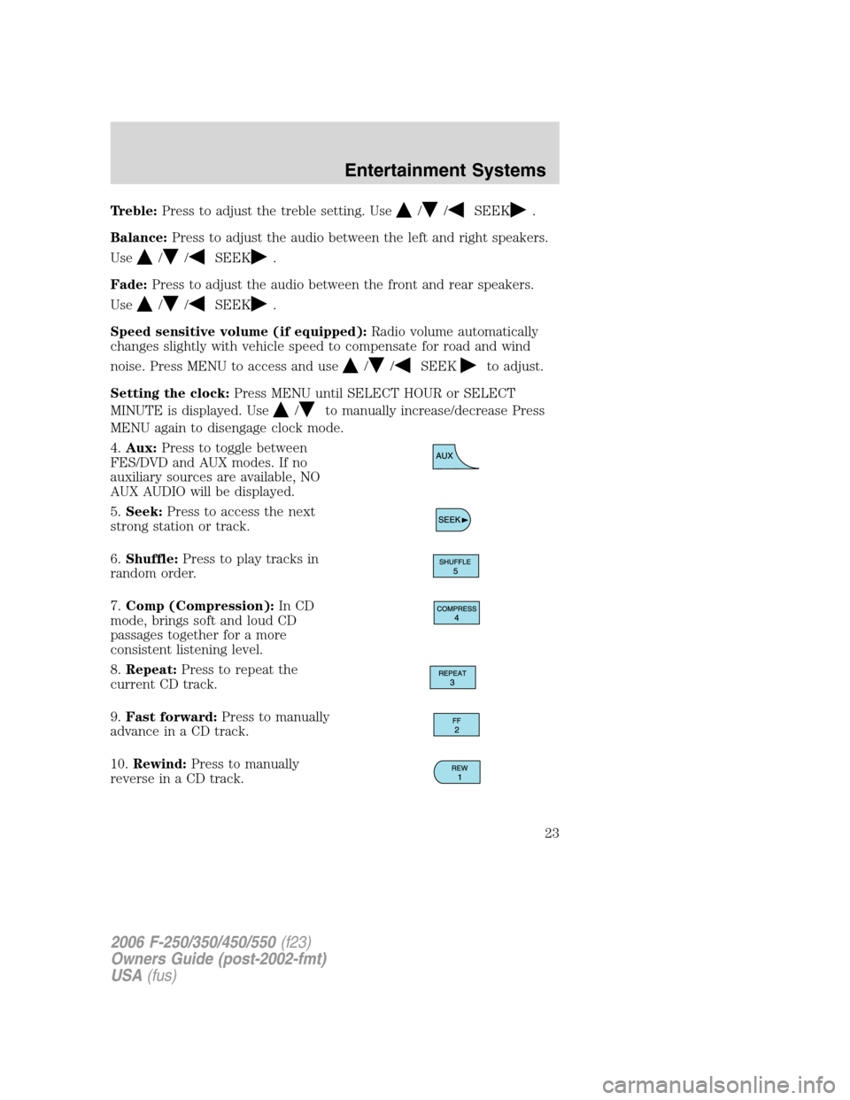
4.Aux:Press to toggle between
FES/DVD and AUX modes. If no
auxiliary sources are available, NO
AUX AUDIO will be displayed.
5.Seek:Press to access the next
strong station or track.
6.Shuffle:Press to play tracks in
random order.
7.Comp (Compression):In CD
mode, brings soft and loud CD
passages together for a more
consistent listening level.
8.Repeat:Press to repeat the
current CD track.
9.Fast forward:Press to manually
advance in a CD track.
10.Rewind:Press to manually
reverse in a CD track.
2006 F-250/350/450/550(f23)
Owners Guide (post-2002-fmt)
USA(fus)
Entertainment Systems
23
Page 26 of 312

Fade:Press to adjust the audio between the front and rear speakers.
Use
//SEEK.
Speed sensitive volume (if equipped):Radio volume automatically
changes slightly with vehicle speed to compensate for road and wind
noise. Press MENU to access and use
//SEEKto adjust.
Setting the clock:Press MENU until SELECT HOUR or SELECT
MINUTE is displayed. Press
//SEEKto adjust the
hours/minutes.
Autoset:Allows you to set the strongest local radio stations without
losing your original manually set preset stations for AM/FM1/FM2 . Press
MENU to access. Use
//SEEKto set.
When the six strongest stations are filled, the station stored in preset 1
will begin playing. If there are less than six strong stations, the system
will store the last one in the remaining presets.
Dolby noise reduction:In tape mode, this feature reduces tape noise
and hiss. Press
//SEEKto cycle ON/OFF. The Dolby noise
reduction system is manufactured under license from Dolby Laboratories
Licensing Corporation. Dolby and double-D are registered trademarks of
Dolby Laboratories Licensing Corporation.
5.AUX:Press to toggle between
FES/DVD and AUX modes. If no
auxiliary sources are available, NO
AUX AUDIO will be displayed. To return to radio mode, press AM/FM.
6.Tape eject:Press to eject a tape.
7.Shuffle:Press to play CD tracks
in random order.
8.Compress (Compression):In
CD mode, brings soft and loud CD
passages together for a more
consistent listening level.
2006 F-250/350/450/550(f23)
Owners Guide (post-2002-fmt)
USA(fus)
Entertainment Systems
26
Page 29 of 312

3.Menu:Press to toggle through
the following modes:
Autoset:Allows you to set the strongest local radio stations without
losing your original manually set preset stations for AM/FM1/FM2 . Press
MENU to access. Use
//SEEKto set.
When the six strongest stations are filled, the station stored in preset 1
will begin playing. If there are less than six strong stations, the system
will store the last one in the remaining presets.
Bass:Press to adjust the bass setting. Use
//SEEK.
Treble:Press to adjust the treble setting. Use
//SEEK.
Balance:Press to adjust the audio between the left and right speakers.
Use
//SEEK.
Fade:Press to adjust the audio between the front and rear speakers.
Use
//SEEK.
Speed sensitive volume (if equipped):Radio volume automatically
changes slightly with vehicle speed to compensate for road and wind
noise. Press MENU to access and use
//SEEKto adjust.
Setting the clock:Press MENU until SELECT HOUR or SELECT
MINUTE is displayed. Press
//SEEKto adjust the
hours/minutes.
4.Aux:Press to toggle between
FES/DVD and AUX modes. If no
auxiliary sources are available, NO
AUX AUDIO will be displayed.
5.Seek:Press to access the next
strong station or track.
6.Shuffle:Press to play tracks in
random order.
2006 F-250/350/450/550(f23)
Owners Guide (post-2002-fmt)
USA(fus)
Entertainment Systems
29
Page 43 of 312

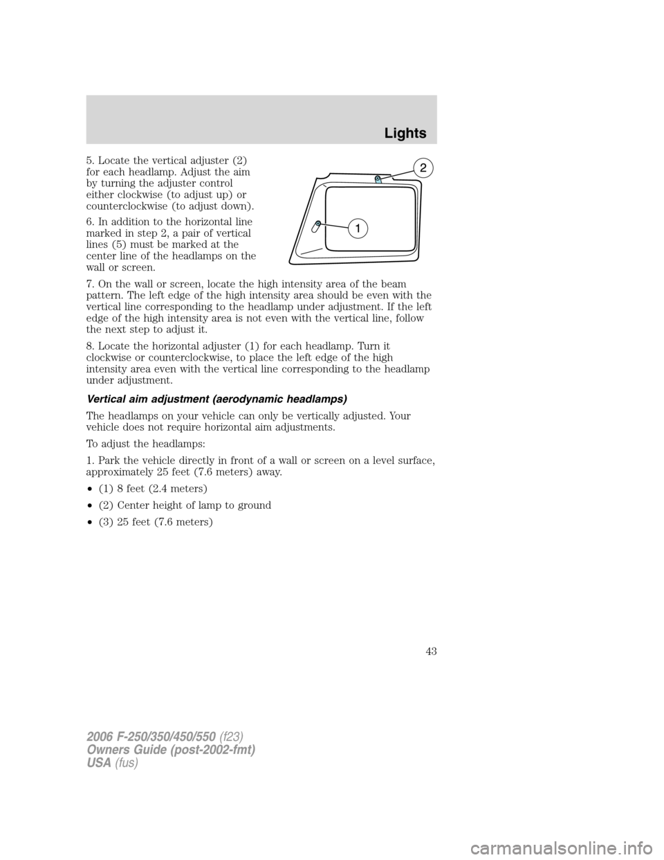
5. Locate the vertical adjuster (2)
for each headlamp. Adjust the aim
by turning the adjuster control
either clockwise (to adjust up) or
counterclockwise (to adjust down).
6. In addition to the horizontal line
marked in step 2, a pair of vertical
lines (5) must be marked at the
center line of the headlamps on the
wall or screen.
7. On the wall or screen, locate the high intensity area of the beam
pattern. The left edge of the high intensity area should be even with the
vertical line corresponding to the headlamp under adjustment. If the left
edge of the high intensity area is not even with the vertical line, follow
the next step to adjust it.
8. Locate the horizontal adjuster (1) for each headlamp. Turn it
clockwise or counterclockwise, to place the left edge of the high
intensity area even with the vertical line corresponding to the headlamp
under adjustment.
Vertical aim adjustment (aerodynamic headlamps)
The headlamps on your vehicle can only be vertically adjusted. Your
vehicle does not require horizontal aim adjustments.
To adjust the headlamps:
1. Park the vehicle directly in front of a wall or screen on a level surface,
approximately 25 feet (7.6 meters) away.
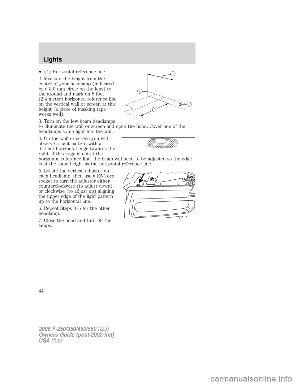
•(1) 8 feet (2.4 meters)
•(2) Center height of lamp to ground
•(3) 25 feet (7.6 meters)
2006 F-250/350/450/550(f23)
Owners Guide (post-2002-fmt)
USA(fus)
Lights
43
Page 44 of 312

•(4) Horizontal reference line
2. Measure the height from the
center of your headlamp (indicated
by a 3.0 mm circle on the lens) to
the ground and mark an 8 foot
(2.4 meter) horizontal reference line
on the vertical wall or screen at this
height (a piece of masking tape
works well).
3. Turn on the low beam headlamps
to illuminate the wall or screen and open the hood. Cover one of the
headlamps so no light hits the wall.
4. On the wall or screen you will
observe a light pattern with a
distinct horizontal edge towards the
right. If this edge is not at the
horizontal reference line, the beam will need to be adjusted so the edge
is at the same height as the horizontal reference line.
5. Locate the vertical adjuster on
each headlamp, then use a E5 Torx
socket to turn the adjuster either
counterclockwise (to adjust down)
or clockwise (to adjust up) aligning
the upper edge of the light pattern
up to the horizontal line.
6. Repeat Steps 3–5 for the other
headlamp.
7. Close the hood and turn off the
lamps.
2006 F-250/350/450/550(f23)
Owners Guide (post-2002-fmt)
USA(fus)
Lights
44
Page 47 of 312
2. Remove the four screws from the
top and bottom front of the
headlamp assembly.
3. Press the retaining clip at the top
of the headlamp assembly while
pulling the assembly straight out.
If removing the lamp is difficult,
removing the four screws along
the top of the grill will help
provide more clearance.
4. Disconnect the electrical
connector by squeezing the release
tab and pushing the connector
forward and then pulling it
rearward.
5. Remove the bulb assembly by
turning it counterclockwise and
pulling it straight out.
Handle a halogen headlamp bulb carefully and keep out of
children’s reach. Grasp the bulb only by its plastic base and do
not touch the glass. The oil from your hand could cause the bulb to
break the next time the headlamps are operated.
Install the new bulb(s) in reverse order.
2006 F-250/350/450/550(f23)
Owners Guide (post-2002-fmt)
USA(fus)
Lights
47
Page 48 of 312
Replacing park/turn and sidemarker lamp bulbs (aerodynamic)
1. Make sure that the headlamp control is in the OFF position and open
the hood.
2. Remove the four screws from the
top and bottom front of the
headlamp assembly.
3. Press the retaining clip at the top
of the headlamp assembly while
pulling the assembly straight out.
If removing the lamp is difficult,
removing the four screws along
the top of the grill will help
provide more clearance.
4. Remove the bulb assembly, (1)
sidemarker or (2) park/turn by
turning it counterclockwise and
pulling it straight out.
5. Pull the old bulb out from the
socket.
Install the new bulb(s) in reverse order.
2006 F-250/350/450/550(f23)
Owners Guide (post-2002-fmt)
USA(fus)
Lights
48