Page 47 of 198
Downloaded from www.Manualslib.com manuals search engine The anti-theft alarm system for thetailgate is deactivated when theluggage compartment is unlockedwith a key (4-door models) or theremote control (all models). Afterclosure, the alarm is once againarmed.
Vehicles with 3.0 l Duratec-VE/-ST or 2.5 l Duratec-VEengine
Note: Unlocking a front door with akey will not deactivate this alarm.
On vehicles with enhanced security(certain markets only), the anti-theftalarm system is deactivated bypressing the unlock button on theremote control.
To deactivate with a non-remote key,open the driver’s door with themechanical key. This starts a 12second delay chime before the alarmsounds. During this period the alarmsystem can be deactivated by turningthe key in the ignition to position II.
45
Alarm
Page 69 of 198
Downloaded from www.Manualslib.com manuals search engine ELECTRIC WINDOWS
WARNING
Before operating the electricwindows you should verify theyare free of obstructions and ensurethat children and/or pets are not inthe proximity of window openings.Failure to do so could result in seriouspersonal injury. It is the primaryresponsibility of the supervising adultsto never leave a child unattended ina vehicle and to never leave the keysin an unattended vehicle.
Note: When the switches areoperated often during a short periodof time, the system might becomeinoperable for a certain time toprevent damage due to overheating.
Note: The electric windows areconnected to the vehicle’s globalopening and closing feature. SeeGlobal opening and closing (page 40).
Switch on the ignition to operate theelectric windows.
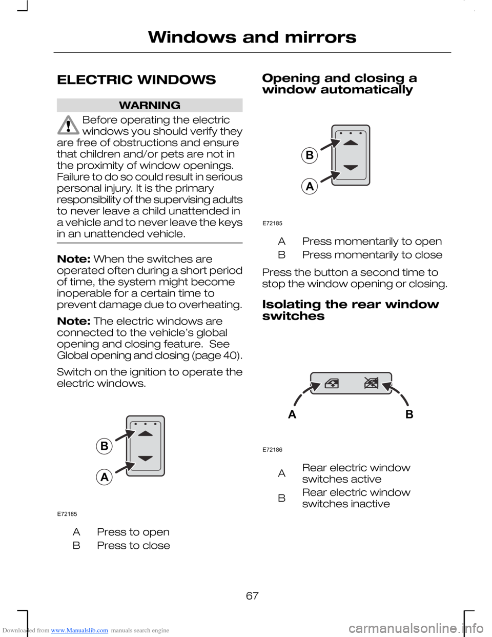
Press to openA
Press to closeB
Opening and closing awindow automatically
Press momentarily to openA
Press momentarily to closeB
Press the button a second time tostop the window opening or closing.
Isolating the rear window
switches
Rear electric windowswitches activeA
Rear electric windowswitches inactiveB
67
Windows and mirrorsE72185BA E72185BA E72186AB
Page 89 of 198
Downloaded from www.Manualslib.com manuals search engine AUXILIARY HEATER
The auxiliary heater aids in warmingthe engine and the interiorcompartment. It is integrated into thecooling system and is automaticallyswitched on or off depending uponthe coolant temperature.
It is possible that when theprogrammable auxiliary heater isactivated, exhaust fumes may comefrom under the sides of the vehicle.This is normal.
ELECTRIC SUNROOF
WARNING
Before operating the electricsunroof you should verify it isfree of obstructions and ensure thatchildren and/or pets are not in theproximity of the sunroof opening.Failure to do so could result in seriouspersonal injury. It is the primaryresponsibility of the supervising adultsto never leave a child unattended ina vehicle and to never leave the keysin an unattended vehicle.
Note: When the switches areoperated often during a short periodof time, the system might becomeinoperable for a certain time toprevent damage due to overheating.
Note: The electric sunroof isconnected to the vehicle’s globalopening and closing feature. SeeGlobal opening and closing (page 40).
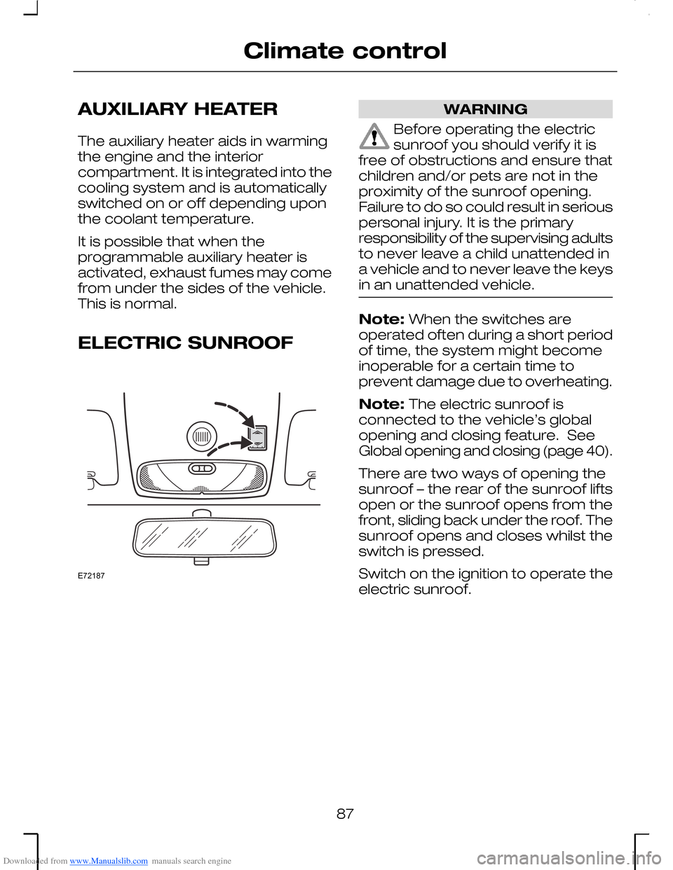
There are two ways of opening thesunroof – the rear of the sunroof liftsopen or the sunroof opens from thefront, sliding back under the roof. Thesunroof opens and closes whilst theswitch is pressed.
Switch on the ignition to operate theelectric sunroof.
87
Climate controlE72187
Page 102 of 198
Downloaded from www.Manualslib.com manuals search engine GENERAL INFORMATION
General points on starting
If the battery has been disconnectedthe vehicle may exhibit some unusualdriving characteristics for approx. 8kilometres (5 miles) afterreconnecting the battery.
This is because the enginemanagement system must realignitself with the engine. Any unusualdriving characteristics during thisperiod may be disregarded.
Starting the engine bytowing or pushing
WARNING
To prevent damage you mustnot push or tow start yourvehicle. Use booster cables and abooster battery. See Using boostercables (page 158).
IGNITION SWITCH
Ignition switch positions
Position 0
WARNING
Never return the key to the 0position when the vehicle is inmotion.
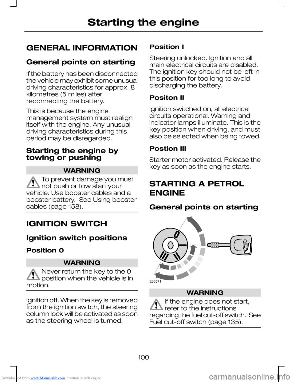
Ignition off. When the key is removedfrom the ignition switch, the steeringcolumn lock will be activated as soonas the steering wheel is turned.
Position I
Steering unlocked. Ignition and allmain electrical circuits are disabled.The ignition key should not be left inthis position for too long to avoiddischarging the battery.
Positon II
Ignition switched on, all electricalcircuits operational. Warning andindicator lamps illuminate. This is thekey position when driving, and mustalso be selected when being towed.
Postion III
Starter motor activated. Release thekey as soon as the engine starts.
STARTING A PETROL
ENGINE
General points on starting
WARNING
If the engine does not start,refer to the instructionsregarding the fuel cut-off switch. SeeFuel cut-off switch (page 135).
100
Starting the engineE66571
Page 103 of 198
Downloaded from www.Manualslib.com manuals search engine Do not operate the starter for longerthan 30 seconds at a time. Releasethe ignition key as soon as the enginehas started. If the engine has notstarted, return the ignition key toposition 0 and repeat the startingprocedure.
Cold/hot engine
WARNING
At temperatures below –20 ºC,turn the ignition key to positionII for at least one second. Thisensures that maximum fuel pressureis established.
Depress the clutch pedal fully andstart the engine without touching theaccelerator.
If the engine does not start within 15seconds, wait for a short period andrepeat the procedure.
If the engine does not start afterthree attempts wait 10 seconds andfollow the Flooded engineprocedure.
Flooded engine
Depress the clutch pedal fully.
Slowly depress the accelerator fully,hold it in this position and start theengine.
If the engine does not start repeatthe Cold/hot engine procedure.
STARTING A DIESEL
ENGINE
General points on starting
WARNING
If the engine does not start,refer to the instructionsregarding the fuel cut-off switch. SeeFuel cut-off switch (page 135).
Do not operate the starter for longerthan 30 seconds. Release the ignitionkey as soon as the engine hasstarted. If the engine has not started,return the ignition key to position 0and repeat the starting procedure.
Cold/hot engine
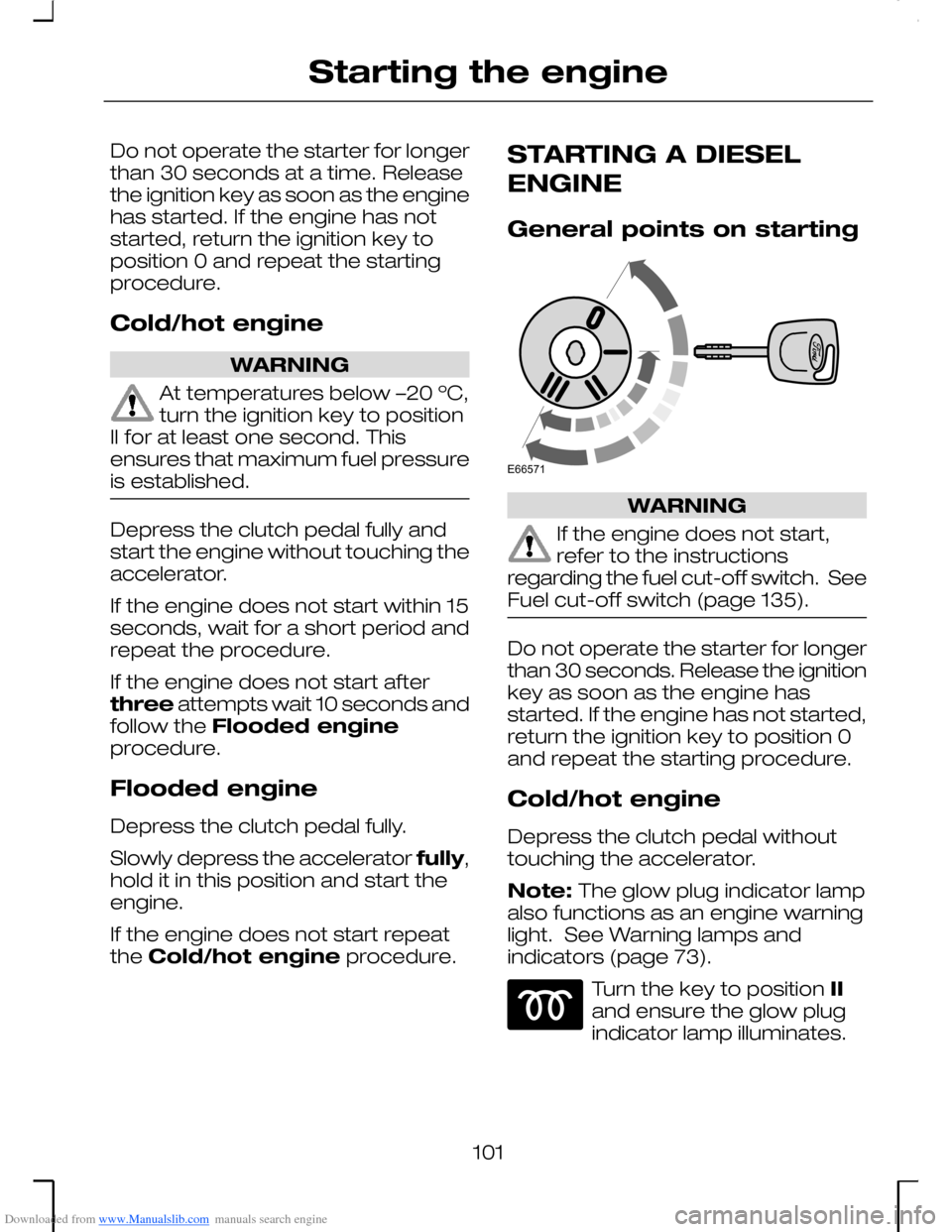
Depress the clutch pedal withouttouching the accelerator.
Note: The glow plug indicator lampalso functions as an engine warninglight. See Warning lamps andindicators (page 73).
Turn the key to position IIand ensure the glow plugindicator lamp illuminates.
101
Starting the engineE66571
Page 130 of 198
Downloaded from www.Manualslib.com manuals search engine WARNING
Driving with a roof load can havea negative influence on thedriveability of the vehicle.
Roof rails (Estate)
The side mounting rails are designedso that racks (for bicycles, skis etc.)from the Ford accessories range canbe fitted. Loads should be evenlydistributed on the cross rails and/orthe side rails. Never place any loadsdirectly onto the roof surface.
Lockable cross rails with fitting keyfrom the Ford accessories range canbe obtained from your dealer.
Note: Take care not to install thecross rails over the rear area of thesunroof in such a way that it wouldrestrict the tilting mechanism.
To minimise wind noise, the twocross rails can be fitted at 30 cmdistance or completely removedwhen they are not in use.
128
Load carryingE72515 E72516
Page 131 of 198
Downloaded from www.Manualslib.com manuals search engine TOWING A TRAILER
Note: Mondeo ST vehicles are notapproved for trailer towing.
The maximum vehicle and trailerpayloads represent technicallybinding values for gradients up to 12% and at an altitude of 1 000 metresabove sea level. In high altituderegions, thinner atmosphere canreduce engine performance so thefollowing restrictions will apply:
Above 1 000 metres, the stipulatedmaximum permitted gross trainweight must be reduced by 10 % forevery 1 000 metres in altitude.
Steep gradients
WARNING
The overrun brake on a trailer isnot controlled by the anti-lockbraking system.
Change down in plenty of timebefore downhill gradients.
For vehicles with an automatictransmission, if downhill modeprovides insufficient braking thenselect manual mode and second orfirst gear as necessary.
ESSENTIAL TOWING
CHECKS
WARNING
If any of the following conditionscannot be met, do not use thetow bar and have it inspected by anexpert.
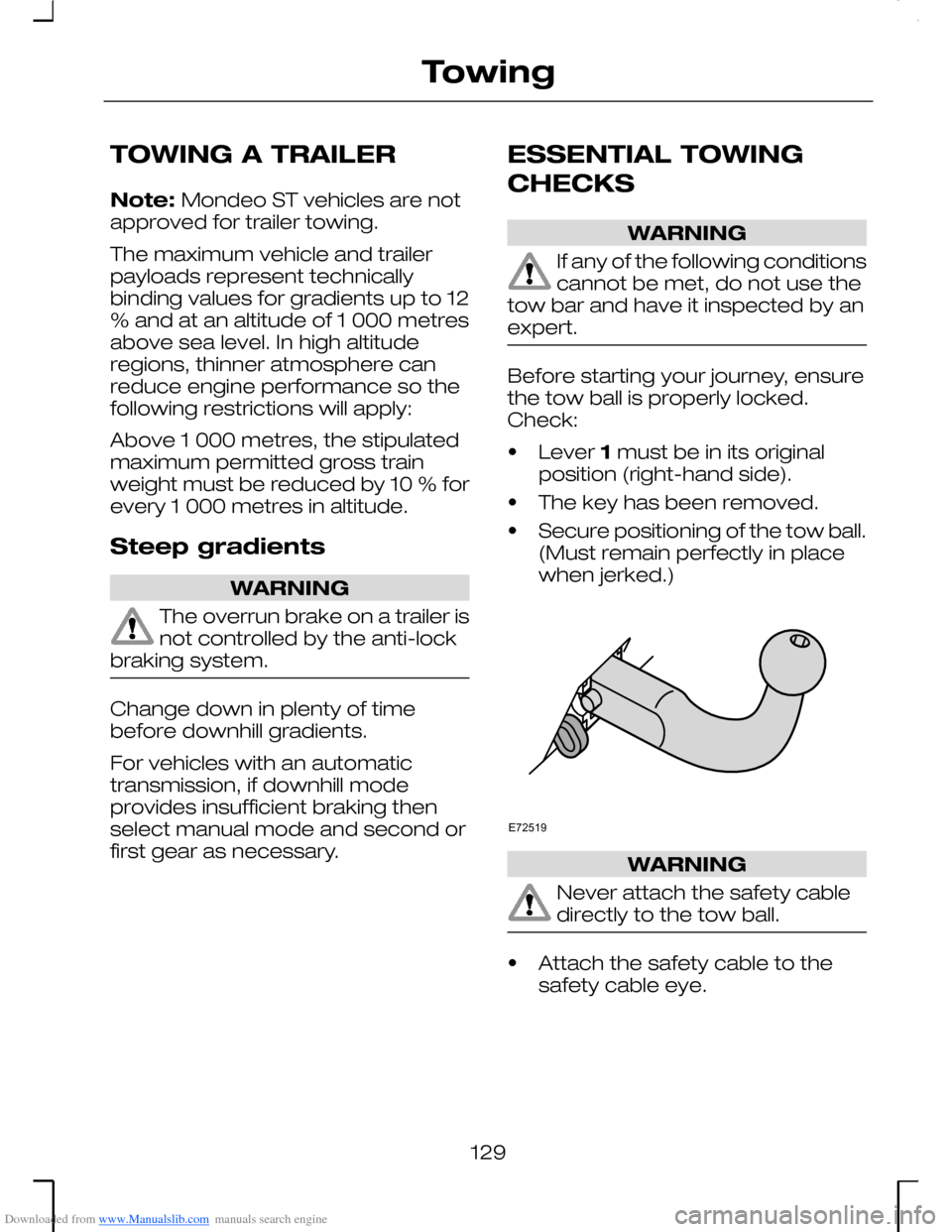
Before starting your journey, ensurethe tow ball is properly locked.Check:
•Lever 1 must be in its originalposition (right-hand side).
•The key has been removed.
•Secure positioning of the tow ball.(Must remain perfectly in placewhen jerked.)
WARNING
Never attach the safety cabledirectly to the tow ball.
•Attach the safety cable to thesafety cable eye.
129
TowingE72519
Page 132 of 198
Downloaded from www.Manualslib.com manuals search engine DETACHABLE TOW BALL
WARNINGS
Remove and reinstall the towball regularly to keep the lockingmechanism working smoothly.
Do not use any tools formounting/dismounting the towball. Do not modify the trailercoupling. Do not disassemble/repairthe tow ball.
To avoid risk of injury, neverunlock the tow ball with thetrailer attached.
To avoid risk of injury, neverleave the detached tow ballunsecured inside the vehicle.
Note: When the tow ball is not inuse, always remove it and secure itwith the strap to the eye on theright-hand side in the rear of theluggage compartment.
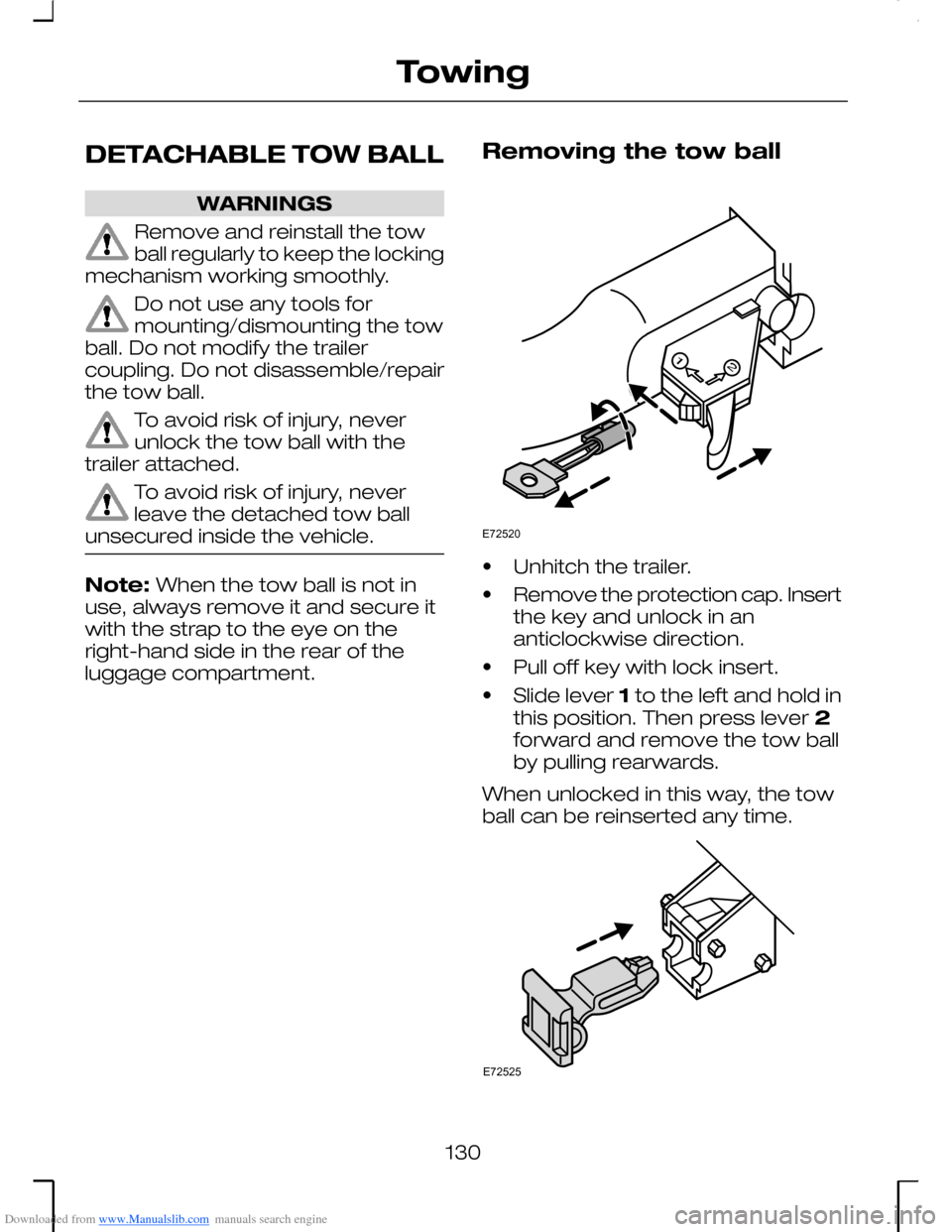
Removing the tow ball
•Unhitch the trailer.
•Remove the protection cap. Insertthe key and unlock in ananticlockwise direction.
•Pull off key with lock insert.
•Slide lever 1 to the left and hold inthis position. Then press lever 2forward and remove the tow ballby pulling rearwards.
When unlocked in this way, the towball can be reinserted any time.
130
TowingE72520 E72525