Page 55 of 128
For Hydromax-equipped vehicles operating under normal
conditions,the noise of the fluid flowing through the booster may be
heard whenever the brake is applied. This condition is normal. Vehicle
service is not required.
If braking performance or pedal response becomes very poor, even when
the pedal is strongly depressed, it may indicate the presence of air in the
hydraulic system or leakage of fluid. Stop the vehicle safely as soon as
possible and seek service immediately.
Anti-lock brake system (ABS)
On vehicles equipped with an anti-lock braking system (ABS), a noise
from the hydraulic pump motor and pulsation in the pedal may be
observed during ABS braking events. Pedal pulsation coupled with noise
while braking under panic conditions or on loose gravel, bumps, wet or
snowy roads is normal and indicates proper functioning of the vehicle’s
anti-lock brake system. The ABS performs a self-check after you start
the engine and begin to drive away. A brief mechanical noise may be
heard during this test. This is normal. If a malfunction is found, the ABS
warning light will come on. If the vehicle has continuous vibration or
shudder in the steering wheel while braking, the vehicle should be
inspected by a qualified service technician.
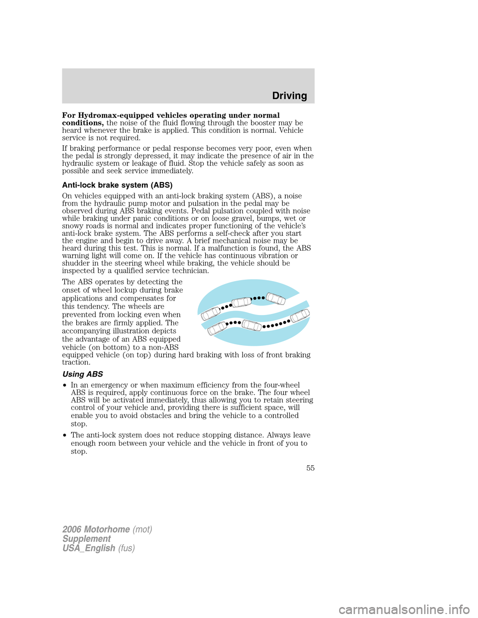
The ABS operates by detecting the
onset of wheel lockup during brake
applications and compensates for
this tendency. The wheels are
prevented from locking even when
the brakes are firmly applied. The
accompanying illustration depicts
the advantage of an ABS equipped
vehicle (on bottom) to a non-ABS
equipped vehicle (on top) during hard braking with loss of front braking
traction.
Using ABS
•In an emergency or when maximum efficiency from the four-wheel
ABS is required, apply continuous force on the brake. The four wheel
ABS will be activated immediately, thus allowing you to retain steering
control of your vehicle and, providing there is sufficient space, will
enable you to avoid obstacles and bring the vehicle to a controlled
stop.
•The anti-lock system does not reduce stopping distance. Always leave
enough room between your vehicle and the vehicle in front of you to
stop.
2006 Motorhome(mot)
Supplement
USA_English(fus)
Driving
55
Page 64 of 128
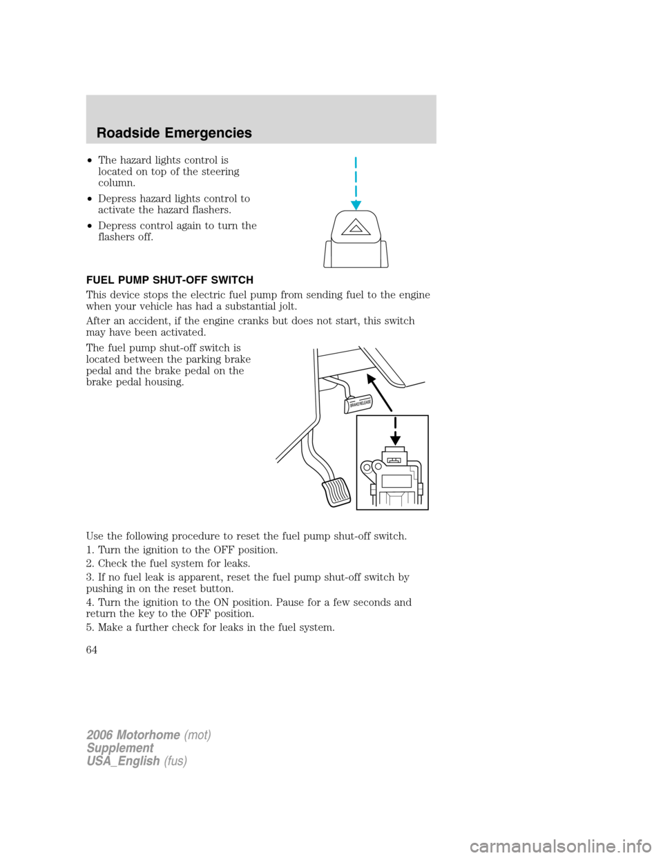
•The hazard lights control is
located on top of the steering
column.
•Depress hazard lights control to
activate the hazard flashers.
•Depress control again to turn the
flashers off.
FUEL PUMP SHUT-OFF SWITCH
This device stops the electric fuel pump from sending fuel to the engine
when your vehicle has had a substantial jolt.
After an accident, if the engine cranks but does not start, this switch
may have been activated.
The fuel pump shut-off switch is
located between the parking brake
pedal and the brake pedal on the
brake pedal housing.
Use the following procedure to reset the fuel pump shut-off switch.
1. Turn the ignition to the OFF position.
2. Check the fuel system for leaks.
3. If no fuel leak is apparent, reset the fuel pump shut-off switch by
pushing in on the reset button.
4. Turn the ignition to the ON position. Pause for a few seconds and
return the key to the OFF position.
5. Make a further check for leaks in the fuel system.
2006 Motorhome(mot)
Supplement
USA_English(fus)
Roadside Emergencies
64
Page 65 of 128
FUSES AND RELAYS
Standard fuse amperage rating and color
COLOR
Fuse
ratingMini
fusesStandard
fusesMaxi
fusesCartridge
maxi
fusesFuse link
cartridge
2A Grey Grey — — —
3A Violet Violet — — —
4A Pink Pink — — —
5A Tan Tan — — —
7.5A Brown Brown — — —
10A Red Red — — —
15A Blue Blue — — —
20A Yellow Yellow Yellow Blue Blue
25A Natural Natural — — —
30A Green Green Green Pink Pink
40A — — Orange Green Green
50A — — Red Red Red
60A — — Blue — Yellow
70A — — Tan — Brown
80A — — Natural — Black
Passenger compartment fuse panel
The fuse panel is located below and to the left of the steering wheel by
the brake pedal. Remove the panel cover to access the fuses.
To remove a fuse use the fuse puller tool provided on the fuse panel
cover.
2006 Motorhome(mot)
Supplement
USA_English(fus)
Roadside Emergencies
65
Page 88 of 128
IDENTIFYING COMPONENTS IN THE ENGINE COMPARTMENT
6.8L V10 engine
1. Engine coolant reservoir
2. Engine oil filler cap
3. Automatic transmission fluid dipstick
4. Power distribution box
5. Air filter assembly
6. Engine oil dipstick
7. Brake fluid reservoir
8. Power steering fluid reservoir
9. Transmission fluid filter (general area—out of view)
2006 Motorhome(mot)
Supplement
USA_English(fus)
Maintenance and Specifications
88
Page 99 of 128
What you should know about fail-safe cooling
If the engine coolant supply is depleted, this feature allows the vehicle to
be driven temporarily before incremental component damage is incurred.
The “fail-safe” distance depends on ambient temperatures, vehicle load
and terrain.
How fail-safe cooling works
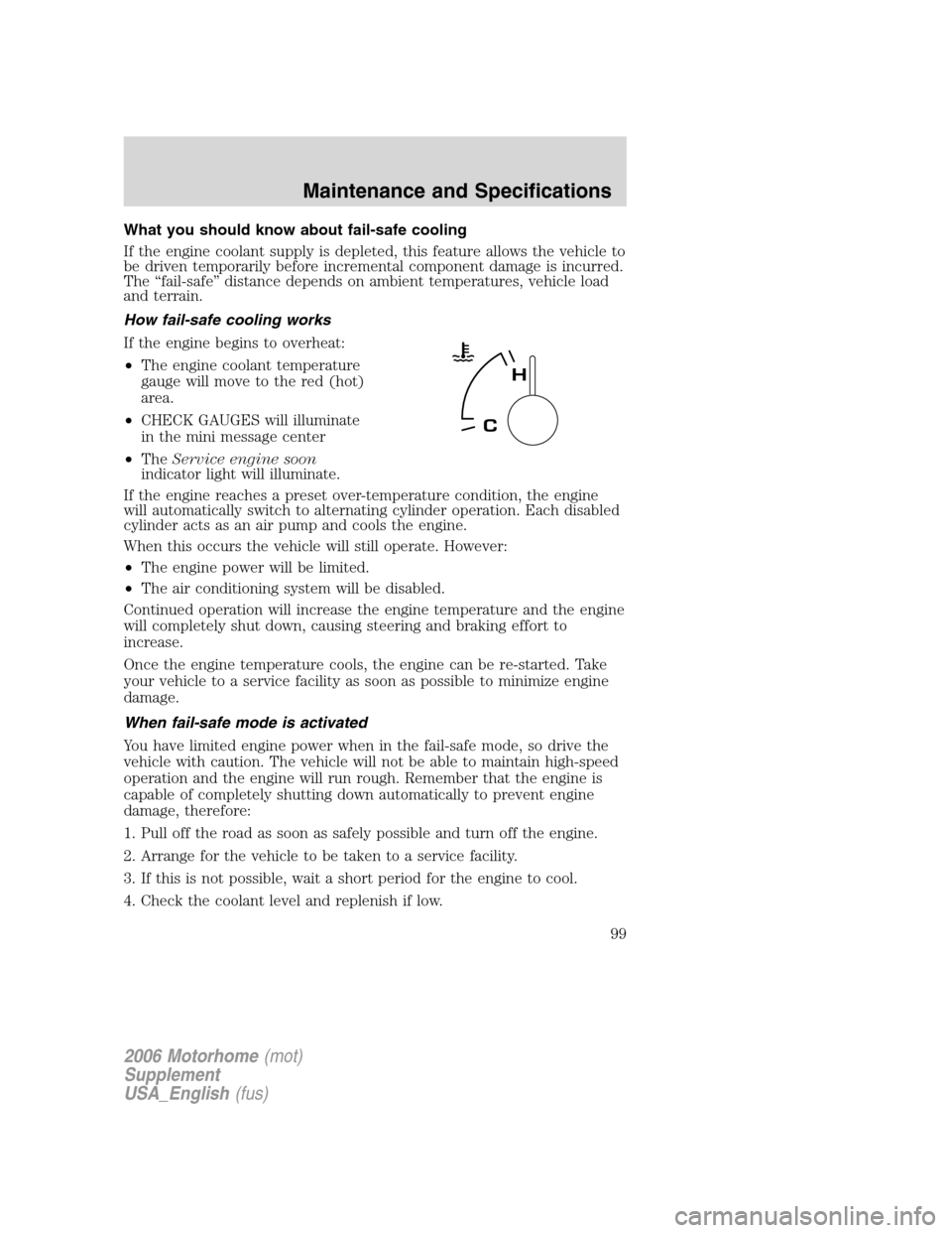
If the engine begins to overheat:
•The engine coolant temperature
gauge will move to the red (hot)
area.
•CHECK GAUGES will illuminate
in the mini message center
•TheService engine soon
indicator light will illuminate.
If the engine reaches a preset over-temperature condition, the engine
will automatically switch to alternating cylinder operation. Each disabled
cylinder acts as an air pump and cools the engine.
When this occurs the vehicle will still operate. However:
•The engine power will be limited.
•The air conditioning system will be disabled.
Continued operation will increase the engine temperature and the engine
will completely shut down, causing steering and braking effort to
increase.
Once the engine temperature cools, the engine can be re-started. Take
your vehicle to a service facility as soon as possible to minimize engine
damage.
When fail-safe mode is activated
You have limited engine power when in the fail-safe mode, so drive the
vehicle with caution. The vehicle will not be able to maintain high-speed
operation and the engine will run rough. Remember that the engine is
capable of completely shutting down automatically to prevent engine
damage, therefore:
1. Pull off the road as soon as safely possible and turn off the engine.
2. Arrange for the vehicle to be taken to a service facility.
3. If this is not possible, wait a short period for the engine to cool.
4. Check the coolant level and replenish if low.
2006 Motorhome(mot)
Supplement
USA_English(fus)
Maintenance and Specifications
99
Page 110 of 128
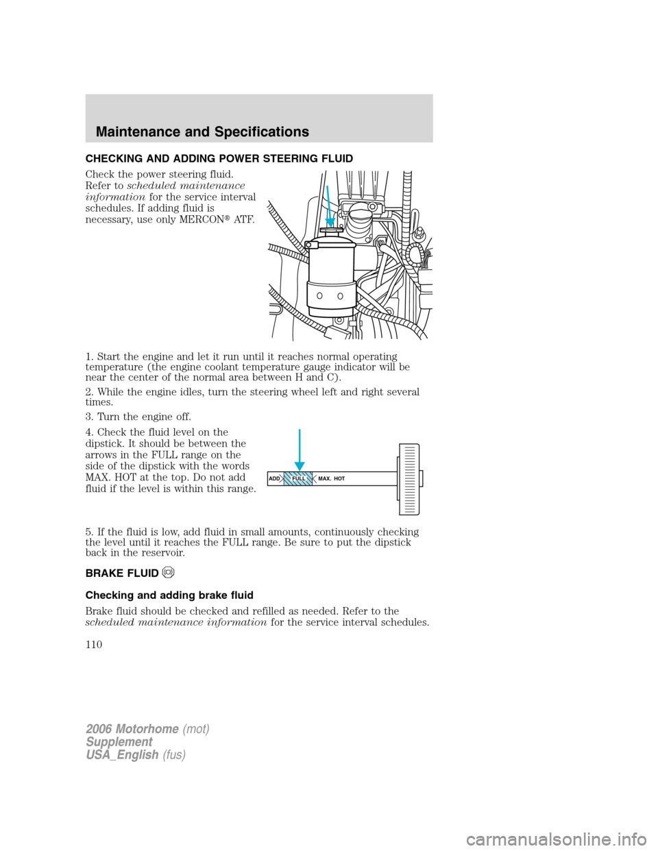
CHECKING AND ADDING POWER STEERING FLUID
Check the power steering fluid.
Refer toscheduled maintenance
informationfor the service interval
schedules. If adding fluid is
necessary, use only MERCON�AT F.
1. Start the engine and let it run until it reaches normal operating
temperature (the engine coolant temperature gauge indicator will be
near the center of the normal area between H and C).
2. While the engine idles, turn the steering wheel left and right several
times.
3. Turn the engine off.
4. Check the fluid level on the
dipstick. It should be between the
arrows in the FULL range on the
side of the dipstick with the words
MAX. HOT at the top. Do not add
fluid if the level is within this range.
5. If the fluid is low, add fluid in small amounts, continuously checking
the level until it reaches the FULL range. Be sure to put the dipstick
back in the reservoir.
BRAKE FLUID
Checking and adding brake fluid
Brake fluid should be checked and refilled as needed. Refer to the
scheduled maintenance informationfor the service interval schedules.
ADD MAX. HOTFULL
2006 Motorhome(mot)
Supplement
USA_English(fus)
Maintenance and Specifications
110
Page 115 of 128
STEERING LINKAGE LUBRICATION POINTS
There are nine lubrication points on the steering linkage shown as “A”.
Refer to theLubricant specificationschart in this chapter for lubricant
type to use.
AIR FILTER MAINTENANCE
Refer toscheduled maintenance informationfor the appropriate
intervals for changing the air filter element.
When changing the air filter element, use only the Motorcraft air filter
element listed. Refer toMotorcraft part numbersin this chapter.
Note:Do not start your engine with the air cleaner removed and do not
remove it while the engine is running.
2006 Motorhome(mot)
Supplement
USA_English(fus)
Maintenance and Specifications
115
Page 118 of 128
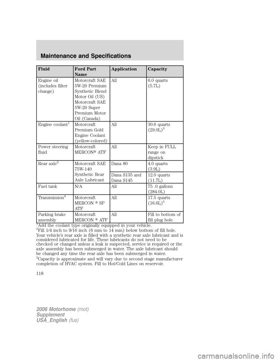
Fluid Ford Part
NameApplication Capacity
Engine oil
(includes filter
change)Motorcraft SAE
5W-20 Premium
Synthetic Blend
Motor Oil (US)
Motorcraft SAE
5W-20 Super
Premium Motor
Oil (Canada)All 6.0 quarts
(5.7L)
Engine coolant
1Motorcraft
Premium Gold
Engine Coolant
(yellow-colored)All 30.6 quarts
(29.0L)3
Power steering
fluidMotorcraft
MERCON�AT FAll Keep in FULL
range on
dipstick
Rear axle
2Motorcraft SAE
75W-140
Synthetic Rear
Axle LubricantDana 80 4.0 quarts
(3.9L)
Dana S135 and
Dana S14512.0 quarts
(11.7L)
Fuel tank N/A All 75 .0 gallons
(284.0L)
Transmission
4Motorcraft
MERCON�SP
AT FAll 17.5 quarts
(16.6L)5
Parking brake
assemblyMotorcraft
MERCON�AT FAll Fill to bottom of
fill plug hole
1Add the coolant type originally equipped in your vehicle.2Fill 1/4 inch to 9/16 inch (6 mm to 14 mm) below bottom of fill hole.
Your vehicle’s rear axle is filled with a synthetic rear axle lubricant and is
considered lubricated for life. These lubricants do not need to be
checked or changed unless a leak is suspected, service is required or the
axle assembly has been submerged in water. The axle lubricant should
be changed any time the rear axle has been submerged in water.
3Capacity is approximate and will vary due to second stage manufacturer
completion of HVAC system. Fill to Hot/Cold Lines on reservoir.
2006 Motorhome(mot)
Supplement
USA_English(fus)
Maintenance and Specifications
118