Page 9 of 238

8
SAFETY
DEVICES
CORRECT USE
OF THE
VEHICLE
WARNING
LIGHTS AND
MESSAGES
IN AN
EMERGENCY
VEHICLE
MAINTENANCE
TECHNICAL
SPECIFICATIONS
INDEX
DASHBOARD
AND CONTROLS
KEY WITH REMOTE CONTROL
fig. 4
The metal insert Ais retractable and it op-
erates:
❒ignition switch;
❒door locks;
❒fuel filler cap locking/unlocking.
To extract the metal insert, press button
B.
To refit it proceed as follows:
❒keep button Bpressed and move the
metal insert A;
❒release button Band turn the metal
insert Auntil hearing the proper lock-
ing click.
THE KEYS
CODE CARD fig. 3
The vehicle is delivered with two copies
of the ignition key and with the CODE
card which bears the following:
Athe electronic code;
Bthe mechanical key code to be given
to the Fiat Dealership when ordering
duplicate keys.
IMPORTANT In order to ensure perfect
efficiency of the electronic devices con-
tained inside the keys, they should never
be exposed to direct sunlight.All the keys and the CODE
card must be handed over to
the new owner when selling
the vehicle.
fig. 3F0N0003mfig. 4F0N0004m
Page 10 of 238
9
SAFETY
DEVICES
CORRECT USE
OF THE
VEHICLE
WARNING
LIGHTS AND
MESSAGES
IN AN
EMERGENCY
VEHICLE
MAINTENANCE
TECHNICAL
SPECIFICATIONS
INDEX
DASHBOARD
AND CONTROLS
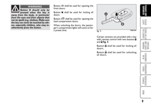
Button Æshall be used for opening the
front doors.
Button Øshall be used for locking all
doors.
Button
∞shall be used for opening the
load compartment doors.
When unlocking the doors, the passen-
ger’s compartment lights will come on for
a preset time.
Button B should only be
pressed when the key is
away from the body, in particular
from the eyes and from objects that
can be spoilt (e.g. clothes). Make sure
the key can never be touched by oth-
ers, especially children, who may in-
advertently press the button.
WARNING
fig. 5F0N0145m
Certain versions are provided with a key
with remote control with two buttons Á
and Ëfig. 5.
Button Áshall be used for locking all
doors.
Button Ëshall be used for unlocking
all doors.
Page 11 of 238

10
SAFETY
DEVICES
CORRECT USE
OF THE
VEHICLE
WARNING
LIGHTS AND
MESSAGES
IN AN
EMERGENCY
VEHICLE
MAINTENANCE
TECHNICAL
SPECIFICATIONS
INDEX
DASHBOARD
AND CONTROLS
Replacing the battery of the key
with remote control fig. 7
Battery replacement:
❒press button Aand move the metal in-
sert Bto the open position;
❒turn the screw Cto :using a fine
bit screwdriver;
❒take out the battery case Dand re-
place the battery Emaking sure that
the bias is correct;
❒refit the battery case Dinside the key
and lock it turning the screw Cto Á.
fig. 7F0N0005m
Request for additional remote
controls
The system can recognise up to 8 keys.
Should a new key with remote control be
necessary, contact a Fiat Dealership, tak-
ing with you the CODE card and the keys,
a personal identity document and the ve-
hicle’s ownership documents.
Dashboard led indications
When locking the doors, led A-fig. 6
switches on for about 3 seconds and than
starts flashing (deterrence function).
Once doors are locked, if one or more
doors or the tailgate are not closed cor-
rectly, the led and direction indicators
start flashing quickly.
fig. 6F0N0114m
Page 12 of 238
11
SAFETY
DEVICES
CORRECT USE
OF THE
VEHICLE
WARNING
LIGHTS AND
MESSAGES
IN AN
EMERGENCY
VEHICLE
MAINTENANCE
TECHNICAL
SPECIFICATIONS
INDEX
DASHBOARD
AND CONTROLS
KEY WITHOUT REMOTE
CONTROL fig. 8
The metal insert of the key Ais fixed.
The key operates:
❒ignition switch;
❒door locks;
❒fuel filler cap locking/unlocking.fig. 8F0N0006m
Used batteries are harmful to
the environment. They should
be disposed of as specified by
law in the special containers
provided, or take them to a Fiat Deal-
ership, which will deal with their dis-
posal.
Page 13 of 238

Type of key
Key without
remote control
Key with remote control
Direction
indicators flashing
(only with key with
remote control)
Deterrence led
12
SAFETY
DEVICES
CORRECT USE
OF THE
VEHICLE
WARNING
LIGHTS AND
MESSAGES
IN AN
EMERGENCY
VEHICLE
MAINTENANCE
TECHNICAL
SPECIFICATIONS
INDEX
DASHBOARD
AND CONTROLS
The main functions that can be activated with the keys (with or without remote control) are the following:
Door
opening
Key turning
counterclockwise
(driver side)
Key turning
counterclockwise
(driver side)
Press briefly
button
Æ
2 flashings
Turning offDoor closing
form the outside
Key turning
clockwise
(driver side)
Key turning
clockwise
(driver side)
Press briefly
button Ø
1 flashing
Turning on glow-
ing steadily for
about 3 seconds
followed by
deterrence led
flashingDead lock
activation
(where provided)
–
–
Double pressing
on button Ø
3 flashings
Double flashing,
followed by
deterrence
led flashingLoad
compartment
unlocking
–
–
Press briefly
button ∞
2 flashings
Deterrence led
flashing
IMPORTANT Window opening operation is a consequence of a door unlocking control; window closing operation
is a consequence of a door locking control.
Window closing
(where provided)
–
–
Long press(over 2 seconds)
on button Ø
1 flashing
Deterrence led
flashing Window opening
(where provided)
–
–
Long press(over 2
seconds)
on button
Æ
2 flashings
Turning off
Page 14 of 238

13
SAFETY
DEVICES
CORRECT USE
OF THE
VEHICLE
WARNING
LIGHTS AND
MESSAGES
IN AN
EMERGENCY
VEHICLE
MAINTENANCE
TECHNICAL
SPECIFICATIONS
INDEX
DASHBOARD
AND CONTROLS
IGNITION
DEVICE
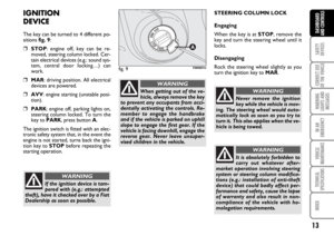
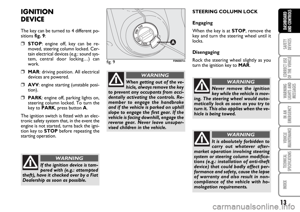
The key can be turned to 4 different po-
sitions fig. 9:
❒STOP: engine off, key can be re-
moved, steering column locked. Cer-
tain electrical devices (e.g.: sound sys-
tem, central door locking…) can
work.
❒MAR: driving position. All electrical
devices are powered.
❒AVV: engine starting (unstable posi-
tion).
❒PARK: engine off, parking lights on,
steering column locked. To turn the
key to PARK, press button A.
The ignition switch is fitted with an elec-
tronic safety system that, in the event the
engine is not started, turns back the igni-
tion key to STOPbefore repeating the
starting operation.STEERING COLUMN LOCK
Engaging
When the key is at STOP, remove the
key and turn the steering wheel until it
locks.
Disengaging
Rock the steering wheel slightly as you
turn the ignition key to MAR.
If the ignition device is tam-
pered with (e.g.: attempted
theft), have it checked over by a Fiat
Dealership as soon as possible.
WARNING
When getting out of the ve-
hicle, always remove the key
to prevent any occupants from acci-
dentally activating the controls. Re-
member to engage the handbrake
and if the vehicle is parked on uphill
slope to engage the first gear. If the
vehicle is facing downhill, engage the
reverse gear. Never leave unsuper-
vised children in the vehicle.
WARNING
fig. 9F0N0007m
Never remove the ignition
key while the vehicle is mov-
ing. The steering wheel would auto-
matically lock as soon as you try to
turn it. This also applies when the ve-
hicle is being towed.
WARNING
It is absolutely forbidden to
carry out whatever after-
market operation involving steering
system or steering column modifica-
tions (e.g.: installation of anti-theft
device) that could badly affect per-
formance and safety, cause the lapse
of warranty and also result in non-
compliance of the vehicle with ho-
mologation requirements.
WARNING
Page 15 of 238
14
SAFETY
DEVICES
CORRECT USE
OF THE
VEHICLE
WARNING
LIGHTS AND
MESSAGES
IN AN
EMERGENCY
VEHICLE
MAINTENANCE
TECHNICAL
SPECIFICATIONS
INDEX
DASHBOARD
AND CONTROLS
INSTRUMENT PANEL
Versions with digital display
ASpeedometer (speed indicator)
BDigital display
CRev counter
DEngine coolant temperature gauge and
excessive temperature warning light
EFuel level gauge with reserve warning
light
Versions with multifunction display
ASpeedometer (speed indicator)
BMultifunction display
CRev counter
DEngine coolant temperature gauge and
excessive temperature warning light
EFuel level gauge with reserve warning
light
F0N0008m
fig. 10
F0N0010m
fig. 11
Page 16 of 238
15
SAFETY
DEVICES
CORRECT USE
OF THE
VEHICLE
WARNING
LIGHTS AND
MESSAGES
IN AN
EMERGENCY
VEHICLE
MAINTENANCE
TECHNICAL
SPECIFICATIONS
INDEX
DASHBOARD
AND CONTROLS
INSTRUMENTS
Instrument background color and type
may vary according to the version.
SPEEDOMETER fig. 12
It shows the engine speed.REV COUNTER fig. 13
Rev counter shows engine rpm.
IMPORTANT The electronic injection
control system gradually shuts off the flow
of fuel when the engine is “over-revving”
resulting in a gradual loss of engine pow-
er.
When the engine is idling, the rev counter
may indicate a gradual or sudden higher-
ing of the speed.
This is normal and takes place for exam-
ple when activating the climate control
system or the fan. In these events a slight
increase in engine idling preserves the bat-
tery charge.
fig. 12F0N0012mfig. 13F0N0013m