Page 310 of 496

STARTING PROCEDURES
CAUTION!
Long periods of engine idling, especially at high
engine speeds, can cause excessive exhaust tempera-
tures which can damage your vehicle. Do not leave
your vehicle unattended with the engine running.
WARNING!
Do not leave animals or children inside parked
vehicles in hot weather; interior heat build up may
cause serious injury or death.
The gear selector must be in the NEUTRAL or PARK
position before you can start the engine. Apply the brakes
before shifting into any driving gear.
Normal Starting
Normal Starting of either a cold or a warm engine is
obtained without pumping or depressing the accelerator
pedal. Turn the key to the “START” position and release
when the engine starts. If the engine has not started
within 3 seconds, slightly depress the accelerator pedal
while continuing to crank. If the engine fails to start
within 15 seconds, turn the key to the “OFF” position,
wait 10 to 15 seconds, then repeat the normal starting
procedure.
Extremely Cold Weather (Below �29°Cor�20° F)
To insure reliable starting at these temperatures, use of an
externally powered electric engine block heater (available
from your dealer) is recommended.
310 STARTING AND OPERATING
Page 317 of 496
PARKING BRAKE
When the parking brake is applied with the ignition
switch on, the brake light in the instrument cluster will
turn on.
NOTE: This light only shows that the parking brake is
applied. It does not show the degree of brake application.
Before leaving the vehicle, make sure that the parking
brake is fully applied and place the gear selector in the
Park position. To release the parking brake, pull out on
the parking brake release located on the left side of the
instrument panel.
When parking on a hill, it is important to set the parking
brake before placing the gear selector in Park, otherwise
the load on the transmission locking mechanism may
make it difficult to move the selector out of park. As an
Parking Brake Release
STARTING AND OPERATING 317
5
Page 319 of 496

by increased pedal travel during application, greater
pedal force required to slow or stop, and potential
activation of the Brake Warning Lamp.
Anti-Lock Brake System — If Equipped
The Anti-Lock Brake System provides increased vehicle
stability and brake performance under most braking
conditions. The system automatically “pumps” the
brakes during severe braking conditions to prevent
wheel lock-up.
WARNING!
Pumping of the Anti-Lock Brakes will diminish
their effectiveness and may lead to an accident.
Pumping makes the stopping distance longer. Just
press firmly on your brake pedal when you need to
slow down or stop.
The ABS light monitors the Anti-Lock Brake
System. The light will come on when the
ignition switch is turned to the ON position
and may stay on for as long as four seconds.
If the ABS light remains on or comes on while driving, it
indicates that the Anti-Lock portion of the brake system
is not functioning and that service is required. However,
the conventional brake system will continue to operate
normally if the BRAKE warning light is not on.
If the ABS light is on, the brake system should be serviced
as soon as possible to restore the benefits of Anti-Lock
brakes. If the ABS light does not come on when the
Ignition switch is turned to the ON position, have the
bulb repaired as soon as possible.
If both the Brake Warning Light and the ABS Light
remain on, the Anti-Lock brakes (ABS) and Electronic
Brake Force Distribution (EBD) systems are not function-
ing. Immediate repair to the ABS system is required.
STARTING AND OPERATING 319
5
Page 320 of 496

When the vehicle is driven over approximately 15 mph
(25 km/h), you may also hear a slight clicking sound as
well as some related motor noises. These noises are the
system performing its self check cycle to ensure that the
ABS system is working properly. This self check occurs
each time the vehicle is started and accelerated past
approximately 15 mph (25 km/h).
ABS is activated during braking under certain road or
stopping conditions. ABS-inducing conditions can in-
clude ice, snow, gravel, bumps, railroad tracks, loose
debris, or panic stops.
You also may experience the following when the brake
system goes into Anti-lock:
•The ABS motor running (it may continue to run for a
short time after the stop),
•the clicking sound of solenoid valves,
•brake pedal pulsations,
•and a slight drop or fall away of the brake pedal at the
end of the stop.
These are all normal characteristics of ABS.
WARNING!
The Anti-Lock Brake System contains sophisticated
electronic equipment that may be susceptible to
interference caused by improperly installed or high
output radio transmitting equipment. This interfer-
ence can cause possible loss of anti-lock braking
capability. Installation of such equipment should be
performed by qualified professionals.
320 STARTING AND OPERATING
Page 364 of 496

WARNING!
Do not connect trailer brakes to your vehicle’s hy-
draulic brake lines. It can overload your brake sys-
tem and cause it to fail. You might not have brakes
when you need them and could have an accident.
Towing any trailer will increase your stopping dis-
tance. When towing you should allow for additional
space between your vehicle and the vehicle in front
of you. Failure to do so could result in an accident.
Towing Requirements — Trailer Lights & Wiring
Whenever you pull a trailer, regardless of the trailer size,
stop lights and turn signals on the trailer are required for
motoring safety.
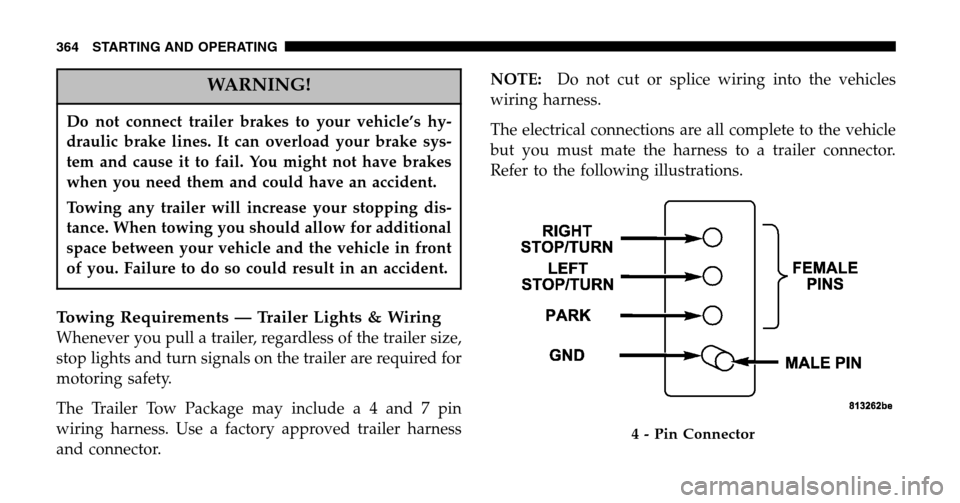
The Trailer Tow Package may includ ea4and7pin
wiring harness. Use a factory approved trailer harness
and connector. NOTE:
Do not cut or splice wiring into the vehicles
wiring harness.
The electrical connections are all complete to the vehicle
but you must mate the harness to a trailer connector.
Refer to the following illustrations.
4 - Pin Connector
364 STARTING AND OPERATING
Page 396 of 496

▫Steering Linkage ......................413
▫ Drive Shaft Universal Joints ..............413
▫ Body Lubrication .....................414
▫ Windshield Wiper Blades ................414
▫ Windshield And Rear Window Washers .....415
▫ Exhaust System ......................415
▫ Cooling System .......................416
▫ Hoses And Vacuum/Vapor Harnesses .......421
▫ Brakes .............................422
▫ Master Cylinder — Brake Fluid Level Check . . 423
▫ Fuel System Hoses ....................425
▫ Automatic Transmission ................425
▫ Front And Rear Wheel Bearings ...........428 ▫
Appearance Care And Protection From
Corrosion ...........................428
▫ Cleaning The Instrument Panel And Underseat
Cup Holders ........................433
� Integrated Power Module (IPM) ............434
� Vehicle Storage ........................437
� Replacement Light Bulbs .................438
� Bulb Replacement ......................439
▫ Headlights ..........................439
▫ Front Park/Turn Signal And Sidemarker
Lights .............................440
▫ Front Fog Light ......................441
▫ Rear Tail, Stop, Turn Signal, Side Marker And
Back-Up Lights .......................442
396 MAINTAINING YOUR VEHICLE
Page 423 of 496

Insure nylon tubing in these areas has not melted or
collapsed.
Inspect all hose connections such as clamps and cou-
plings to make sure they are secure and no leaks are
present.
NOTE: Often, fluid such as oil, power steering fluid,
and brake fluid are used during assembly plant opera-
tions to facilitate the assembly of hoses to couplings.
Therefore, oil wetness at the hose-coupling area is not
necessarily an indication of leakage. Actual dripping of
hot fluid when systems are under pressure (during
vehicle operation), should be noted before hose is re-
placed based on leakage.
NOTE: Inspection of brake hoses should be performed
whenever the brake system is serviced and every engine
oil change. Inspect hydraulic brake hoses for surface
cracking, scuffing, or worn spots. If there is any evidence
of cracking, scuffing, or worn spots, the hose should be replaced immediately! Eventual deterioration of the hose
can take place resulting in a possibility of a burst failure.
WARNING!
Worn brake hoses can burst and cause brake failure.
You could have an accident. If you see any signs of
cracking, scuffing, or worn spots, have the brake
hoses replaced immediately.
Master Cylinder — Brake Fluid Level Check
The fluid level in the master cylinder should be checked
when performing underhood services, or immediately if
the brake system warning light indicates system failure.
Clean the top of the master cylinder area before removing
the cap. Add fluid to bring the level up to the top of the
“FULL” mark on the side of the master cylinder reservoir.
MAINTAINING YOUR VEHICLE 423
7
Page 435 of 496
Cavity Maxi Fuse Description
F4 30 Amp Pink Front Wipers
F9 40 Amp Green Anti-Lock Brake System
(ABS) Pump
F10 40 Amp Green Front Blower
F13 40 Amp Green Electronic Back Light (EBL)
F19 40 Amp Green Body Control Module
(BCM) Feed 1
F20 30 Amp Pink Central Amplifier
F22 30 Amp Pink Seats
F27 40 Amp Green Radiator FanCavity Maxi Fuse Description
F28 40 Amp Green Power Windows
F30 40 Amp Green Headlight Washers (Export
Only)
F31 40 Amp Green Power Sliding Door
F32 40 Amp Green Power Liftgate
MAINTAINING YOUR VEHICLE 435
7