Page 42 of 160
Ignition switch and
steering lockKeysYou receive one master key
and one spare key. Please
consult the information on
the electronic immobiliser
(EWS) if a key is lost or mis-
laid ( 41).Ignition switch and steer-
ing lock, tank filler cap
lock and seat lock are all op-
erated with the same key. If
you wish you can arrange to
have the cases available as
optional accessories fitted
with locks that can be opened
with this key as well.
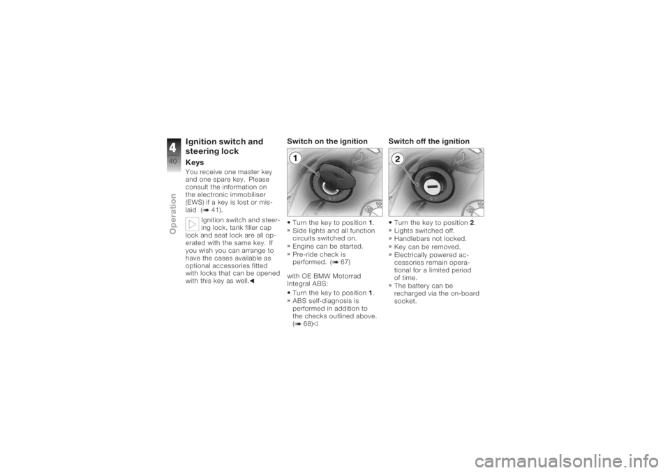
Switch on the ignitionTurn the key to position 1.
Side lights and all function
circuits switched on.
Engine can be started.
Pre-ride check is
performed. ( 67)
with OE BMW Motorrad
Integral ABS: Turn the key to position 1.
ABS self-diagnosis is
performed in addition to
the checks outlined above.
( 68)
Switch off the ignitionTurn the key to position 2.
Lights switched off.
Handlebars not locked.
Key can be removed.
Electrically powered ac-
cessories remain opera-
tional for a limited period
of time.
The battery can be
recharged via the on-board
socket.
440zOperation
Page 44 of 160
electronics, in which case the
enabling signal for starting is
not issued. The
EWS
warning
appears in the multifunction
display.
Always keep the spare key
separately from the ignition
key.
Replacement and extra
keysYou can obtain replacement/
extra keys only through an
authorised BMW Motorrad
dealer. The keys are part of
an integrated security sys-
tem, so the dealer is under
an obligation to check the le-
gitimacy of all applications
for replacement/extra keys.
If you want to have a lost key
barred, you have to bring with
you all the other keys that
belong to the motorcycle. A
key that has been barred can subsequently be cleared and
reactivated for use.
Hazard warning
flashersSwitch on the hazard
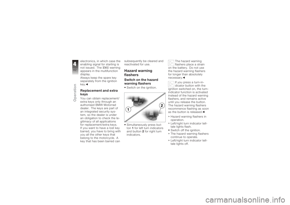
warning flashersSwitch on the ignition.
Simultaneously press but-
ton
1for left turn indicators
and button 2for right turn
indicators. The hazard warning
flashers place a strain
on the battery. Do not use
the hazard warning flashers
for longer than absolutely
necessary.
If you press a turn-in-
dicator button with the
ignition switched on, the turn-
indicator function is activated
instead of the hazard warning
flashers, and remains active
until you release the button.
The hazard warning flashers
recommence flashing as soon
as the button is released.
Hazard warning flashers in
operation.
Left/right turn indicator tell-
tale lights flash.
Switch off the ignition.
The hazard warning flashers
continue to operate.
Left/right turn indicator tell-
tale lights off.
442zOperation
Page 52 of 160
Emergency off switch
(kill switch)1Emergency off switch (kill
switch).
Operating the kill switch
when riding can cause
the rear wheel to lock and
thus cause a fall.
Do not operate the kill switch
when riding.
The emergency off switch is a
kill switch for switching off the
engine quickly and easily. A
Normal operating posi-
tion (run)
B Engine switched off.
You cannot start the
engine unless the kill
switch is in the run position.
Grip heating
OE
1 Grip heating switch
The handlebar grips have
two-stage heating. Grip
heating can be activated only
when the engine is running. The increase in power
consumption caused by
the grip heating can drain the
battery if you are riding at low
engine speeds. If the charge
level is low, grip heating is
switched off to ensure the
battery's starting capability.
450zOperation
Page 54 of 160
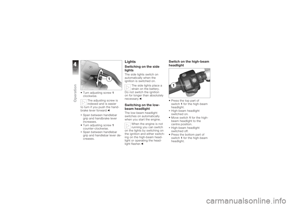
Turn adjusting screw1
clockwise.
The adjusting screw is
indexed and is easier
to turn if you push the hand-
brake lever forward.
Span between handlebar
grip and handbrake lever
increases.
Turn adjusting screw 1
counter-clockwise.
Span between handlebar
grip and handlebar lever de-
creases.
LightsSwitching on the side
lightsThe side lights switch on
automatically when the
ignition is switched on.
The side lights place a
strain on the battery.
Do not switch the ignition
on for longer than absolutely
necessary.Switching on the low-
beam headlightThe low-beam headlight
switches on automatically
when you start the engine.
When the engine is not
running you can switch
on the lights by switching on
the ignition and either switch-
ing on the high-beam head-
light or operating the head-
light flasher.
Switch on the high-beam
headlightPress the top part of
switch 1for the high-beam
headlight.
High-beam headlight
switched on.
Move switch 1for the high-
beam headlight to the
centre position.
High-beam headlight
switched off.
Press the bottom part of
switch 1for the high-beam
headlight.
452zOperation
Page 69 of 160
with OE BMW Motorrad
Integral ABS:Switch on the ignition.
Pre-ride check is
performed. ( 67)
ABS self-diagnosis is per-
formed. ( 68)
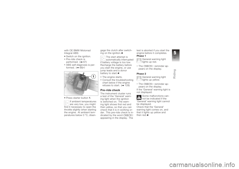
Press starter button 1.
If ambient temperatures
are very low, you might
find it necessary to open the
throttle slightly when starting
the engine. At ambient tem-
peratures below 0 °C, disen- gage the clutch after switch-
ing on the ignition.
The start attempt is
automatically interrupted
if battery voltage is too low.
Recharge the battery before
you start the engine, or use
jump leads and a donor
battery to start.
The engine starts.
Consult the troubleshooting
chart below if the engine
refuses to start. ( 128)
Pre-ride checkThe instrument cluster runs
a test of the 'General' warn-
ing light when the ignition
is switched on. The warn-
ing light shows first red and
then yellow, so that you can
check that it is in working or-
der. This pre-ride check is in-
dicated by the word
CHECK!
appearing in the display. The test is aborted if you start the
engine before it completes.
Phase 1
General warning light
lights up red.
The
CHECK!
reminder ap-
pears on the display.
Phase 2 General warning light
lights up yellow.
The
CHECK!
reminder ap-
pears on the display.
If the 'General' warning light is
not displayed:
Some malfunctions can-
not be indicated if the
'General' warning light cannot
be displayed.
Check that the 'General'
warning light comes on, and
that it lights up yellow and
then red.
567zRiding
Page 87 of 160
Maintenance
General instructions . . . . . . . . . . . 86
Toolkit . . . . . . . . . . . . . . . . . . . . . . . . 86
Engine oil . . . . . . . . . . . . . . . . . . . . . 87
Brake system, general . . . . . . . . . 89
Brake pads . . . . . . . . . . . . . . . . . . . . 90
Brake fluid . . . . . . . . . . . . . . . . . . . . 91
Clutch . . . . . . . . . . . . . . . . . . . . . . . . 94
Tyres . . . . . . . . . . . . . . . . . . . . . . . . . 95
Rims . . . . . . . . . . . . . . . . . . . . . . . . . . 95
Wheels . . . . . . . . . . . . . . . . . . . . . . . 95
Front-wheel stand . . . . . . . . . . . . 104
Rear-wheel stand . . . . . . . . . . . . 105
Bulbs . . . . . . . . . . . . . . . . . . . . . . . . 107
Jump start . . . . . . . . . . . . . . . . . . . 114
Battery . . . . . . . . . . . . . . . . . . . . . . . 115
785zMaintenance
Page 88 of 160

General instructionsThe 'Maintenance' chapter
describes work involving the
replacement of wear parts
that can be performed with
minimum effort.
Special tightening torques are
listed as applicable.
If you are interested in inform-
ation on more extensive work,
we recommend the repair
manual on CD-ROM which
applies to your particular mo-
torcycle. You can obtain a
copy from your authorised
BMW Motorrad dealer.
Some of the work calls for
special tools and a thorough
knowledge of motorcycles.
If you are in doubt consult a
specialist workshop, prefer-
ably your authorised BMW
Motorrad dealer.
ToolkitStandard on-board
toolkit1 Screwdriver with
reversible bladeRemoving and installing turn
indicator glass
Disconnecting leads from
battery terminals
2 Torx wrench, T25 Removing and installing
body panels
Removing and installing bat-
tery retainer 3 Screwdriver, small
Removing and installing turn
indicator glass
On-board toolkit service
kitYour authorised BMW Mo-
torrad dealer can provide the
on-board toolkit service kit
that you will need if you are
considering undertaking more
extensive work.
You will find information
on undertaking work of
this nature in the Repair
Manual on the CD-ROM
also obtainable from your
authorised BMW Motorrad
dealer.
786zMaintenance
Page 117 of 160
with fully insulated crocodile
clips at both ends.Jump-starting with a
donor-battery voltage
higher than 12 V can damage
the vehicle electronics.
Make sure that the battery
of the donor vehicle has a
voltage rating of 12 V.
If it is not standing firmly,
the motorcycle could
topple in the course of the
operations described below.
Always make sure that the
motorcycle is stable and
firmly supported.
When jump-starting the en-
gine, do not disconnect the
battery from the on-board
electrical system.
Remove the battery-com-
partment cover ( 117)
Run the engine of the donor
vehicle during jump-starting. Begin by connecting one
end of the red jump lead
to the positive terminal of
the discharged battery and
the other end to the pos-
itive terminal of the donor
battery.
Then connect one end of
the black jump lead to the
negative terminal of the
donor battery, and the other
end to the negative terminal
of the discharged battery.
Start the engine of the
vehicle with the discharged
battery in the usual way; if
the engine does not start,
wait a few minutes before
repeating the attempt
in order to protect the
starter motor and the donor
battery.
Allow both engines to idle
for a few minutes before
disconnecting the jump
leads.Disconnect the jump lead
from the negative termin-
als first, then disconnect the
second lead from the posit-
ive terminals.
Installing battery-compart-
ment cover ( 118)
BatteryMaintenance instructionsCorrect upkeep, recharging
and storage will prolong the
life of the battery and are es-
sential if warranty claims are
to be considered.
Compliance with the points
below is important in order to
maximise battery life:
Keep the surface of the bat-
tery clean and dry
Do not open the battery
Do not top up with water
Be sure to read and com-
ply with the instructions for
7115zMaintenance