Page 185 of 227

Mobility
183Reference
At a glance
Controls
Driving tips
Communications
Navigation
Entertainment
procedures with correspondingly trained per-
sonnel. Due to the high voltage involved, there
is a danger to life and limb when work is carried
out improperly.<
High beams, parking lamps
The illustration shows the front left side of the
engine compartment.
High beams
Bulb 55 watts, H 7
1.Remove the cover cap1 by pressing the tab
and removing the cover cap upward.
2.Press the bulb holder from above to release
it.
3.Remove the bulb holder.
4.Remove and replace the bulb.
The lamp H7 is pressurized; wear eye
protection and protective gloves. Other-
wise there is a danger of injuries if the bulb is
accidentally damaged during replacement.<
Parking lamps
Bulb 10 watts
Bulb holder and reflector are one unit and
are replaced together.<
1.Turn the bulb holder2 to the right and
remove.
2.Press the snap connection on the plug con-
nector, pull off the bulb holder and replace.
Front turn signal, side marker
Your BMW is equipped with two turn signal
lamps per side in the front.
Turn signal lamp 1
Bulb 21 watts, WY 21 SV
The illustration shows the front right side of the
engine compartment.
1.Press the lever shown:
>downward for the right turn signal
>upward for the left turn signal
2.Remove the bulb holder towards the rear.
3.Remove and replace the bulb.
Turn signal lamp 2
Bulb 21 watts, WY 21 SV
The bulb for the turn signal lamp 2 can be
replaced via the wheel well.
The illustration shows the front left side of the
vehicle.
1.Steering turned all the way to the left or
right.
2.Turn off the light, switch off the ignition and
remove the remote control from the ignition
lock.
3.Unscrew the bolt 1 with the open-ended
wrench from the onboard toolkit, refer to
page182.
Page 186 of 227

Replacing components
184 4.Turn the cover around the rear securing
point2 upward while simultaneously pulling
it out of the trim panel at the bottom.
5.Turn the bulb holder to the left and remove,
refer to arrow.
6.Remove and replace the bulb.
Side markers
Bulb 5 watts, WY5W ST
The bulb can be replaced via a cover at the front
of the wheel well, refer to the description for
turn signal lamp 2.
1.The bulb holder of the sidemarker lamp is
located toward the outside of the vehicle
next to the bulb holder of turn signal lamp 2.
2.Turn the bulb holder to the left and remove.
3.Remove and replace the bulb.
Side turn signals
Bulb 5 watts, WY 5 W
1.Press against the front edge of the lamp
with the tip of your finger, then push it to the
rear, release the snap connection at the
front and take it off the trim strip.2.Turn the bulb holder to the left by 905 and
remove.
3.Remove and replace the bulb.
Tail lamps
The roadside parking, rear and brake
lamps are LEDs. The backup lamps are
equipped with long-life bulbs. Please contact a
BMW center in case of a malfunction.<
1Turn signals
2Roadside parking, rear and brake lamp
3Backup lamp
4Reflector
Rear turn signals
Bulb 21 watts, PY 21 W
The illustration shows the recess on the left
side of the luggage compartment.
1.Remove the cover.
2.Unclip the bulb holder and remove.
3.Apply gentle pressure to the bulb while
turning it to the left for removal and replace-
ment.
Page 187 of 227

Mobility
185Reference
At a glance
Controls
Driving tips
Communications
Navigation
Entertainment
License plate lamps
Bulb 5 watts, WY 5 W
1.Push a screwdriver from the left under the
lamp and pry out the lamp toward the right.
2.Turn the bulb holder to the left by 905 and
remove.
3.Remove and replace the bulb.
Repairing flat tire with
M Mobility System
To repair a flat tire, an M Mobility System is pro-
vided in the BMW M6. Using this system you
can apply a sealant in the inside of the tire, seal
off the damaged area, restore the tire inflation
pressure and then continue driving.
Safety measures in case of a breakdown:
park the vehicle as far as possible from
passing traffic and on solid ground. Switch on
the hazard warning flashers.
Lock the steering wheel in straight-ahead set-
ting of the wheels. Set the handbrake and
engage the first or reverse gear. Have all vehicle
occupants get out of the vehicle and ensure
that they remain outside the immediate area in a
safe place, such as behind a guardrail.
If a warning triangle or portable hazard warning
lamp is required, set it up on the roadside at an
appropriate distance from the rear of the vehi-
cle. Comply with all safety guidelines and regu-
lations.<
Preparation
The M Mobility System is located in the lug-
gage compartment under the floor panel flap.
Do not remove foreign bodies which have pen-
etrated the tire if possible.
Corresponding information on using the
M Mobility System are also provided on
the device.<
Before using the M Mobility System,
observe the information on the sealant
bottle.<
Pull the sticker for the speed limit off the sealant
bottle and apply it to the steering wheel.
Please observe the best-by date on the
sealant bottle.<
The M Mobility System consists of
1Sealant bottle and sticker with speed limit
2Filling hose from sealant bottle to wheel
Page 188 of 227

Replacing components
186
Model with pressure gauge on hose*
3Connector and cable for lighter socket
4Mounting for sealing bottle
5Compressor
6On/Off switch
7Pressure gauge for indicating tire inflation
pressure
8Screw on pressure gauge for reducing tire
inflation pressure
9Connecting hose for connecting compres-
sor and sealant bottle or compressor and
wheel
Connector, cable and connecting hose are
stored in the compressor housing.
Model with pressure gauge integrated
in housing*
3Connector and cable for lighter socket
4Mounting for sealing bottle
5Compressor
6On/Off switch
7Pressure gauge for indicating tire inflation
pressure
8Button for reducing tire inflation pressure9Connecting hose for connecting compres-
sor and sealant bottle or compressor and
wheel
Connector, cable and connecting hose are
stored on underside of compressor.
Using M Mobility System
To repair a flat tire with the M Mobility System,
proceed as follows:
>Fill sealant into wheel, refer to page186.
>Distribute sealant, refer to page187.
>Produce tire inflation pressure, refer to
page187.
Filling sealant into wheel
Strictly comply with the specified order,
otherwise highly pressurized sealant
could escape.<
1.Shake sealant bottle.
2.Screw hose9 onto connection of sealant
bottle.
3.For model with pressure gauge on hose:
Make sure that screw8 on pressure gauge
is closed.
4.Screw dust cap off valve of defective wheel
and screw filling hose2 of sealant bottle
onto valve.
5.Insert sealant bottle on compressor hous-
ing so that it is positioned upright.
6.Make sure that device is switched off,
position 0.
7.Insert connector3 into lighter socket in
vehicle interior, refer to page93.
Page 189 of 227

Mobility
187Reference
At a glance
Controls
Driving tips
Communications
Navigation
Entertainment
8.With the ignition switched on, refer to
page50:
Switch on the device and allow to run for
approx. 3 minutes to fill wheel with sealant.
It is not important what inflation pressure
the tire has after filling.
9.Switch off device.
10.Remove connecting hose from connection
of sealant bottle and tire valve.
Stow the M Mobility System in the vehicle
again.
Distributing sealant
Immediately drive approx. 2 miles/3 km so that
sealant is evenly distributed in tire.
Do not exceed a maximum speed of
35 mph/60 km/h. Do not drop below
12 mph/20 km/h if possible.<
Producing tire inflation pressure
1.After approx. 2 miles/3 km, stop at suitable
location.
2.Screw compressor hose9 directly onto tire
valve.
3.Insert connector 3 in lighter socket in vehi-
cle interior.
4.Correct tire inflation pressure to 29 psi/
200 kPa. With the ignition switched on:
>Increase inflation pressure: switch on
device, position I. To check currently set
inflation pressure, briefly switch off
device.
Do not allow compressor to run
longer than 10 minutes, otherwise
the device will overheat and may be dam-
aged.<
>Reduce inflation pressure: press but-
ton8 or turn screw8 on pressure gauge.
If the inflation pressure is not held, drive
the vehicle again, refer to Distributing
sealant. Then repeat steps 1 to 4 once.
Using the M Mobility System can be ineffective
with tire damage from a size of approx. 0.16 in/
4 mm. Please contact the nearest BMW center,
refer to page192, or a workshop that works according to BMW repair procedures with cor-
respondingly trained personnel if the tire can-
not be made ready for driving with the
M Mobility System.<
The tire inflation pressure must be at least
29 psi/200 kPa. Otherwise do not con-
tinue driving.<
Continue driving
Do not exceed the permissible maximum
speed of 50 mph/80 km/h, otherwise
accidents can occur.<
Reinitialize the Flat Tire Monitor.
For details, refer to page74.
Have the defective tire and the sealant bottle of
the M Mobility System replaced as soon as
possible.<
Changing wheels
Safety precautions in the event of a flat
tire or wheel change: park the vehicle as
far as possible from passing traffic and on solid
ground. Switch on the hazard warning flashers.
Lock the steering wheel in straight-ahead set-
ting of the wheels. Set the handbrake and
engage a driving position with the selector
lever.
Have all vehicle occupants get out of the vehicle
and ensure that they remain outside the imme-
diate area in a safe place, such as behind a
guardrail.
If a warning triangle or portable hazard warning
lamp is required, set it up on the roadside at an
appropriate distance from the rear of the vehi-
cle. Comply with all safety guidelines and regu-
lations.
Change the wheel only on a level, firm surface
which is not slippery. The vehicle or the jack
could slip to the side if you attempt to raise the
vehicle on a soft or slippery surface such as
snow, ice, tiles, etc.
Position the jack on a firm support surface.
Do not use a wooden block or similar object as a
support base for the jack, as this would prevent
it from extending to its full support height and
reduce its load-carrying capacity.
Page 190 of 227

Replacing components
188 To avoid serious or fatal injury: never lie under
the vehicle, and never start the engine while it is
supported by the jack.<
What you will need
To avoid rattling noises later on, note the posi-
tions of the tools before removing them, then
return them to their initial positions after com-
pleting work.
1Chock
*
2Vehicle jack*
3Lug wrench*
The tools are located in the hollow of the spare
wheel
*.
Spare wheel*
1.Pull back lock1, fold open clamp lock2
completely and loosen the belt3.
2.Remove the cover4.
3.Take the tool mount out of the spare wheel.
4.Remove the spare wheel.
Preparing wheel change
1.Observe the safety precautions above.
2.Prevent the vehicle from rolling:
Place the chock behind the front wheel on
the other side of the vehicle, or on inclines,
in front of this wheel. On a steep grade, take
other steps to prevent the vehicle from roll-
ing.
3.Loosen the lug bolts a half turn.
Jacking up vehicle
The jacking points for the car jack are located in
the positions shown.
1.Position the vehicle jack at the jacking point
closest to the wheel so that the entire sur-
face of the jack base rests on the ground
perpendicularly beneath the jacking point.
The vehicle jack is designed for
changing wheels only. Do not attempt
to raise another vehicle model with it or to
raise any load of any kind. To do so could
cause accidents and personal injury.<
2.Guide the jack head into the rectangular
recess of the jacking point when cranking
up, refer to illustration detail.
3.Jack the vehicle up until the wheel you are
changing is raised from the ground.
Page 191 of 227

Mobility
189Reference
At a glance
Controls
Driving tips
Communications
Navigation
Entertainment
Mounting a wheel
1.Unscrew the lug bolts and remove the
wheel.
2.Remove accumulations of mud or dirt from
the mounting surfaces of the wheel and
hub. Also clean the lug bolts.
3.Position the new wheel or spare wheel.
Secure the wheel by screwing at least two
lug bolts into opposite bolt holes.
When you mount wheels other than Genu-
ine BMW light-alloy wheels, different lug
bolts may also be required.
4.Screw in the remaining lug bolts. Tighten all
the bolts securely in a diagonal pattern.
5.Lower the vehicle and remove the jack from
beneath the vehicle.
After mounting
1.Tighten the lug bolts in a diagonal pattern.
To ensure safety, always have the
lug bolts checked with a calibrated
torque wrench as soon as possible to
ensure that they are tightened to the speci-
fied torque. The tightening torque is
88.5 lb ft/120 Nm.<
2.Check and correct the tire inflation pressure
at the earliest opportunity.
Protect valve stems and valve stem
seal caps against dirt and contamina-
tion. Dirt in valve stems is a frequent source
of gradual air loss.<
3.Initialize the Flat Tire Monitor, refer to
page74, and the Sequential Manual Trans-
mission, refer to After changing wheels/
tires on page174.
4.Replace the damaged tire as soon as possi-
ble and have the new wheel/tire balanced.
Stowing wheel and tools
1.Lay the wheel in the tool mounting.
2.Lay the cover on the mounting.
3.Center the wheel and cover relative to the
lashing eyes5.4.Hook the belt into the lashing eyes.
5.Completely open the tensioning lock.
6.Thread the belt3 through the axis6 of the
tensioning lock without twisting it and ten-
sion it by hand.
7.Tighten the belt firmly with the tensioning
lock by opening and closing the lock several
times.
8.Fold the tensioning lock closed and stow
the protruding belt end.
Driving with spare wheel
With certain wheel-and-tire combinations
the size of the spare wheel differs from
that of the other wheels. The spare wheel is
equivalent to them in all load and speed ranges.
However, to restore the original state, the nor-
mal wheel should be remounted as soon as
possible.<
Vehicle battery
Maintenance
The battery is 100 % maintenance-free, i.e., the
electrolyte will last for the life of the battery
when the vehicle is operated in a temperate cli-
mate.
Your BMW center will be glad to advise in all
matters concerning the battery.
Charging battery
Only charge the battery in the vehicle via the
terminals in the engine compartment with the
engine switched off. For the connections, refer
to Jump starting on page192.
Page 192 of 227

Replacing components
190
Disposal
After replacement, have old batteries dis-
posed of by your BMW center or deposit
them at a recycling center. Maintain the battery
in an upright position for transport and storage.
Always secure the battery to prevent it from tip-
ping over during transport.<
Power failure
Following a temporary interruption of the power
supply, the operation of some equipment is lim-
ited and must be reinitialized. Individual settings
are also lost and must be updated:
>Seat, mirror and steering wheel memory
The position must be stored again, refer to
page40.
>Time and Date
The values must be updated, refer to
page67.
>Radio
Stations must be stored again if necessary,
refer to page132.
>Navigation system
Wait until the system starts, refer to
page123.
Fuses
Never attempt to repair a blown fuse, and
do not replace a defective fuse with a sub-
stitute of another color or amperage rating, as
this could lead to overloading of the wiring, ulti-
mately resulting in a fire in the vehicle.<
Spare fuses and a pair of plastic tweezers are
located in the compartment for the onboard tool
kit, refer to page182.
Information on fuse allocation is located below
the bracket for the onboard tool kit, see below.
In glove compartment
1.Press the button on the back in the center of
partition1 and pull out the partition upward,
arrow2.
2.Press the coupling downward, arrow3, and
fold the lid 4 forward.
In luggage compartment
Fold the cover under the floor mat upward and
remove the bracket for the onboard tool kit.
Information on fuse allocation1 and additional
fuses2 are provided there.
 1
1 2
2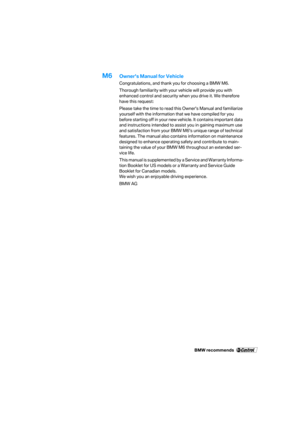 3
3 4
4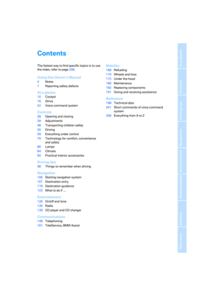 5
5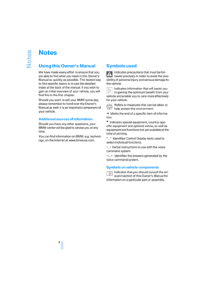 6
6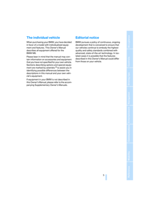 7
7 8
8 9
9 10
10 11
11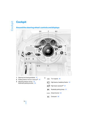 12
12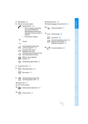 13
13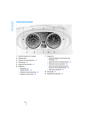 14
14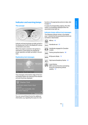 15
15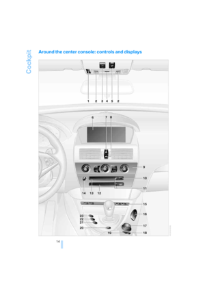 16
16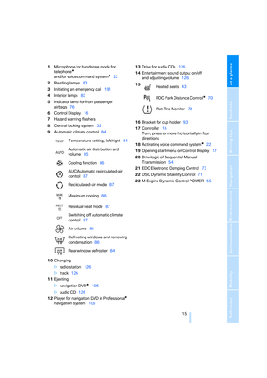 17
17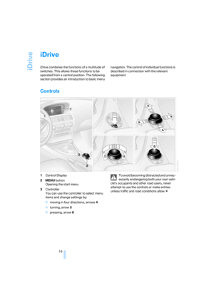 18
18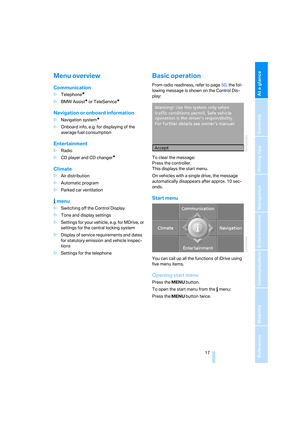 19
19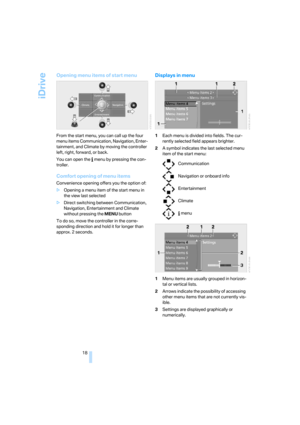 20
20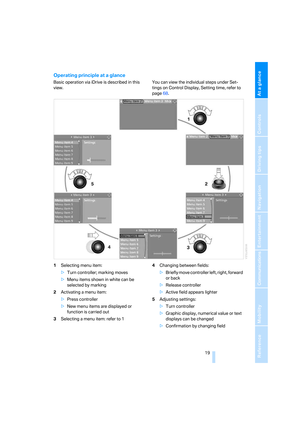 21
21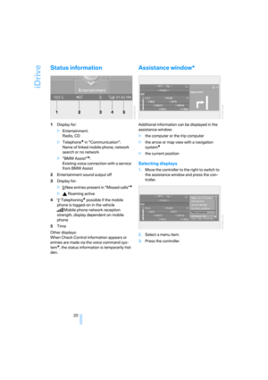 22
22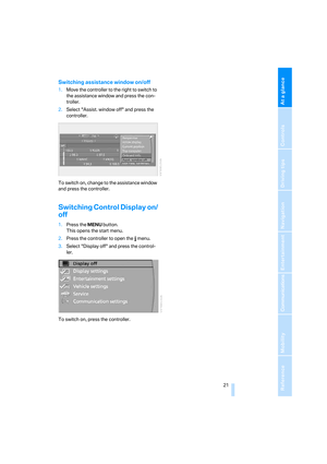 23
23 24
24 25
25 26
26 27
27 28
28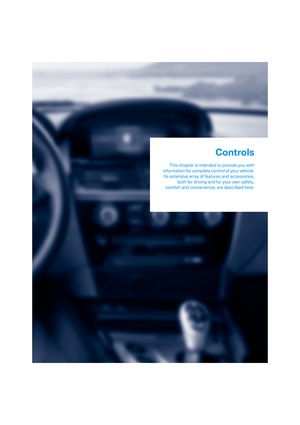 29
29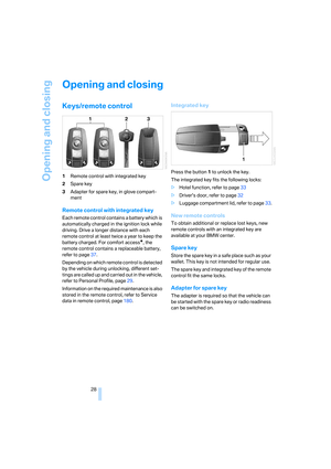 30
30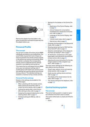 31
31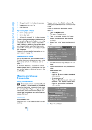 32
32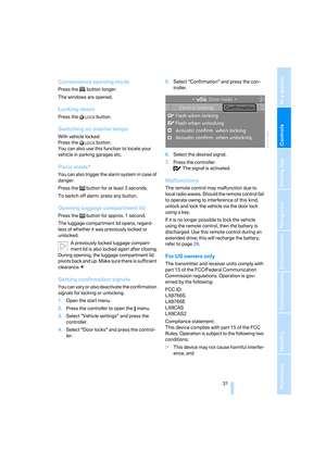 33
33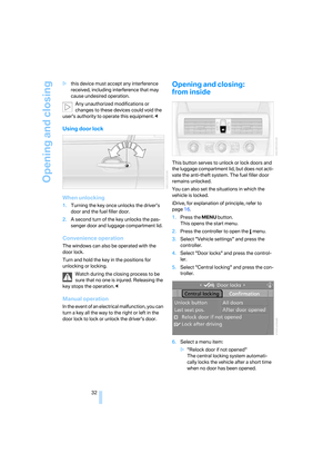 34
34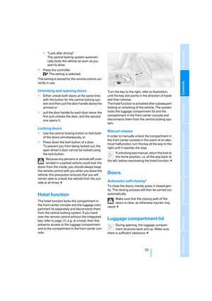 35
35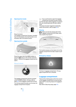 36
36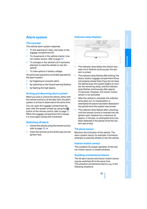 37
37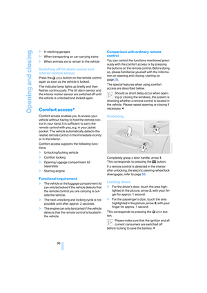 38
38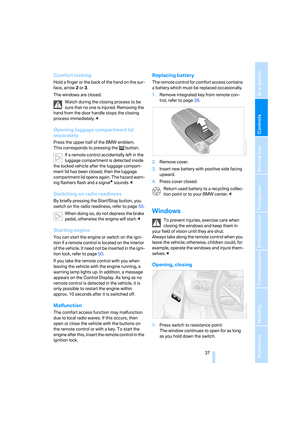 39
39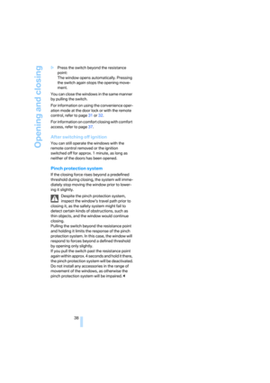 40
40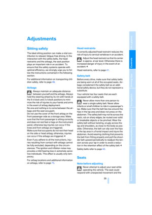 41
41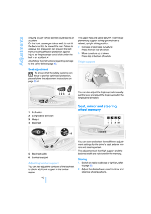 42
42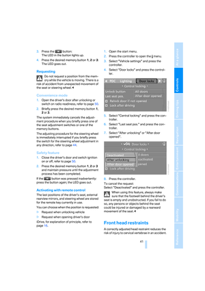 43
43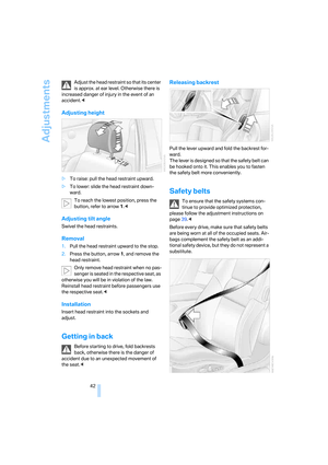 44
44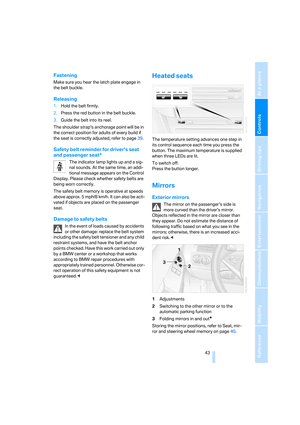 45
45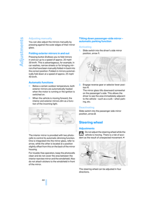 46
46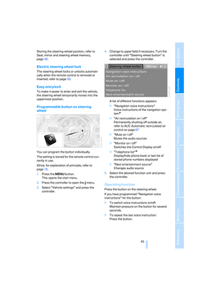 47
47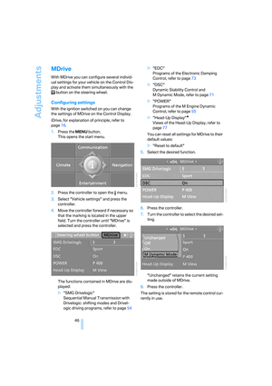 48
48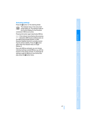 49
49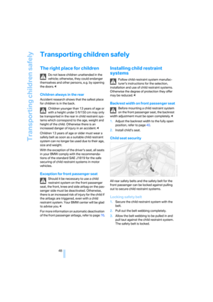 50
50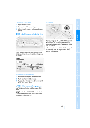 51
51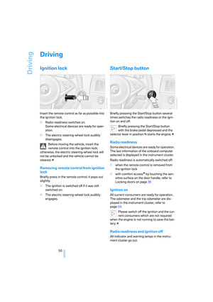 52
52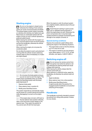 53
53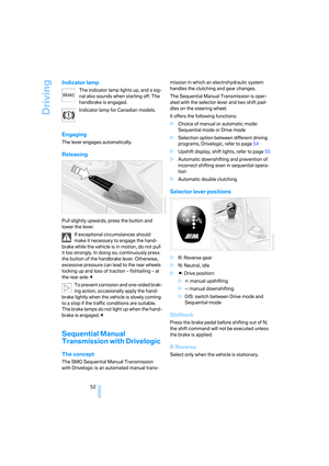 54
54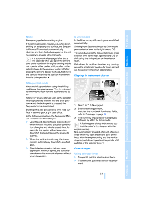 55
55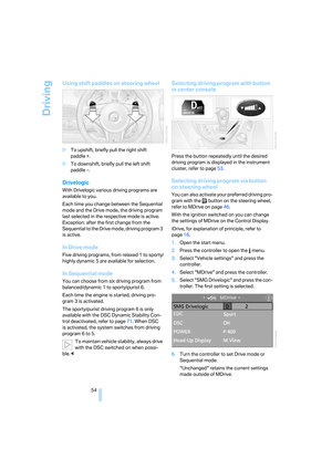 56
56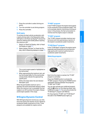 57
57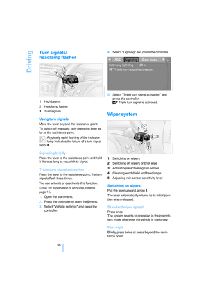 58
58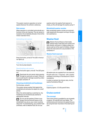 59
59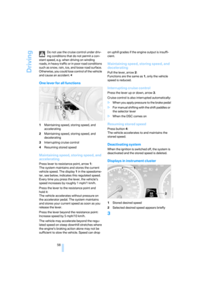 60
60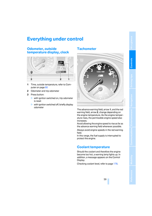 61
61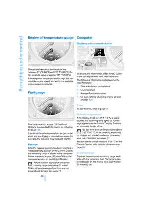 62
62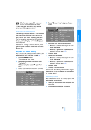 63
63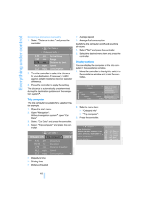 64
64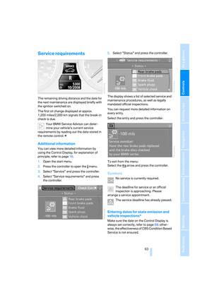 65
65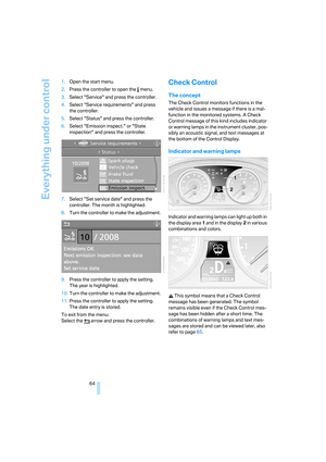 66
66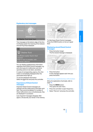 67
67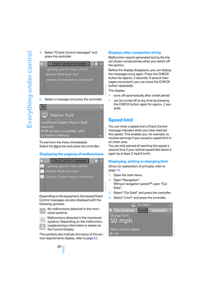 68
68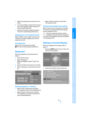 69
69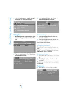 70
70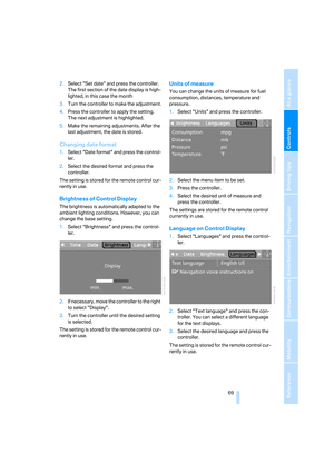 71
71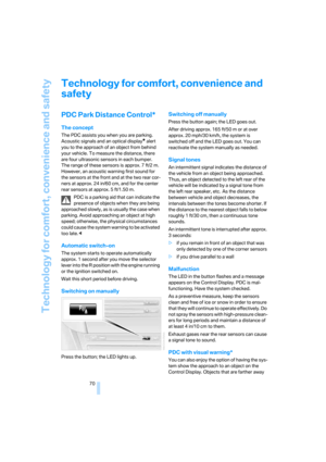 72
72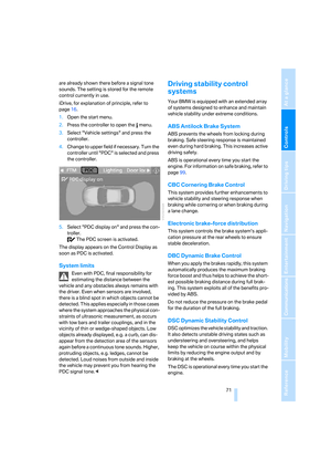 73
73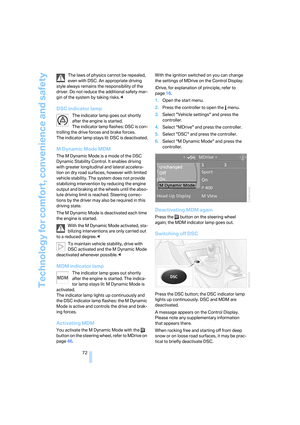 74
74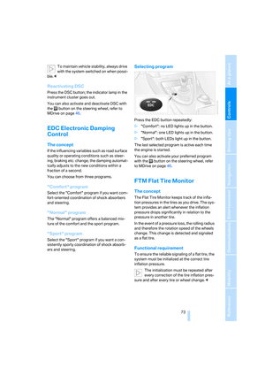 75
75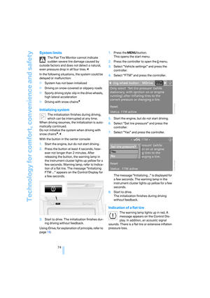 76
76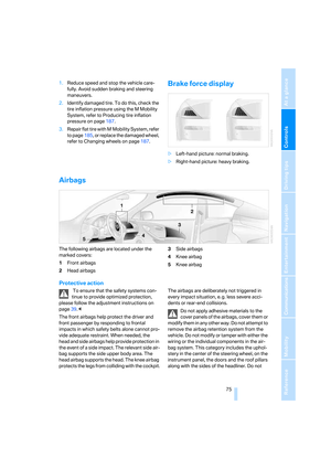 77
77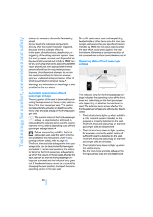 78
78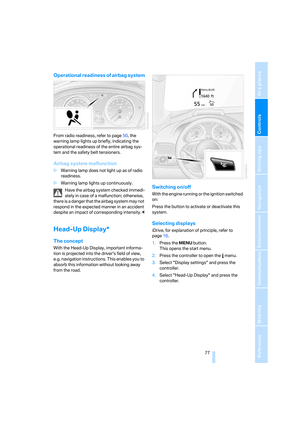 79
79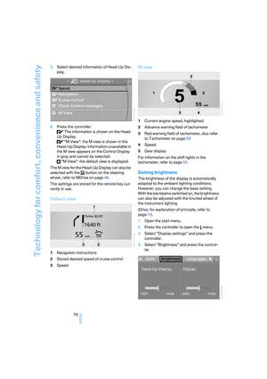 80
80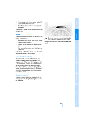 81
81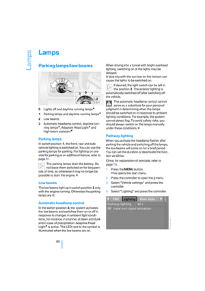 82
82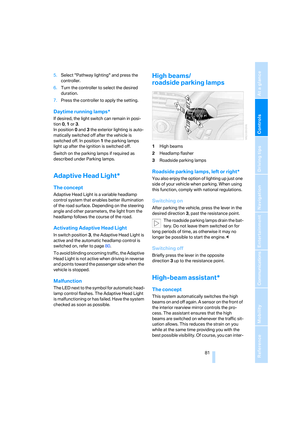 83
83 84
84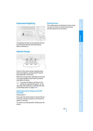 85
85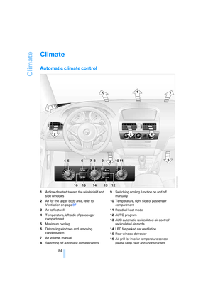 86
86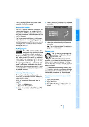 87
87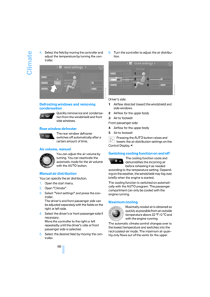 88
88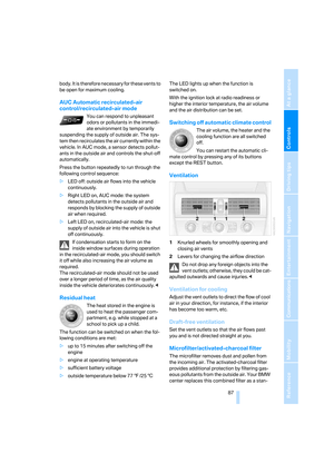 89
89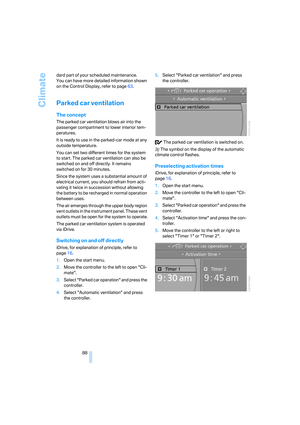 90
90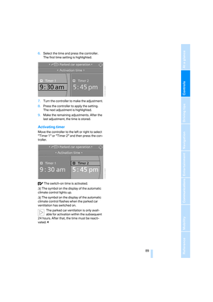 91
91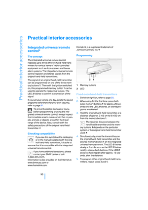 92
92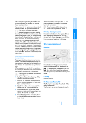 93
93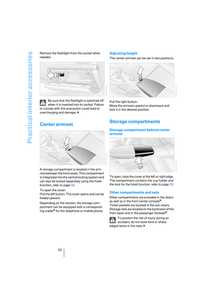 94
94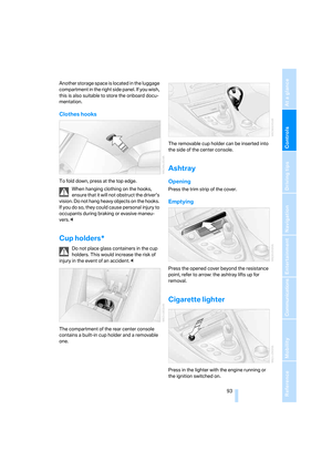 95
95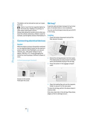 96
96 97
97 98
98 99
99 100
100 101
101 102
102 103
103 104
104 105
105 106
106 107
107 108
108 109
109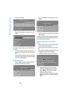 110
110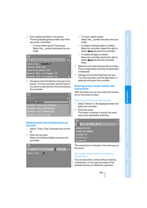 111
111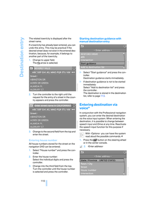 112
112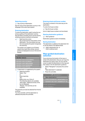 113
113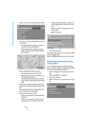 114
114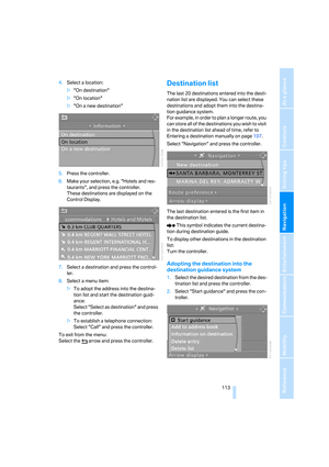 115
115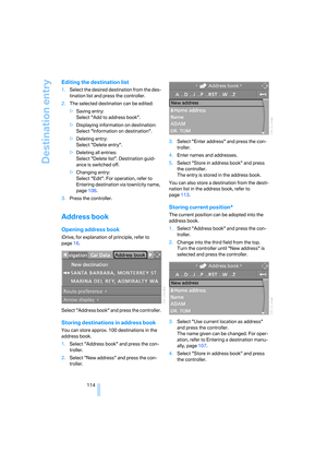 116
116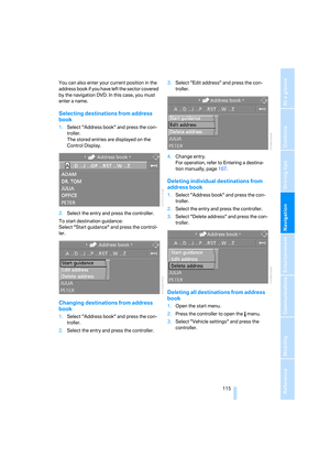 117
117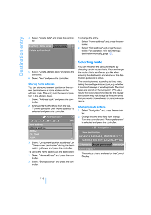 118
118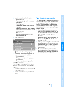 119
119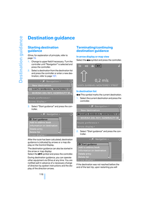 120
120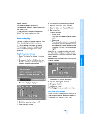 121
121 122
122 123
123 124
124 125
125 126
126 127
127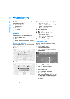 128
128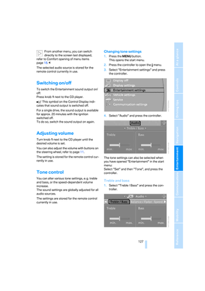 129
129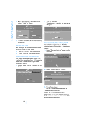 130
130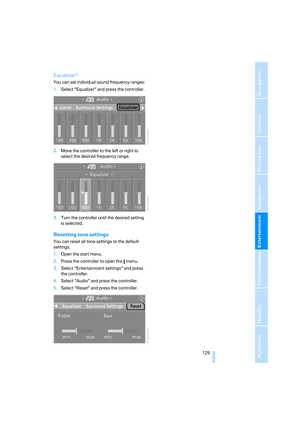 131
131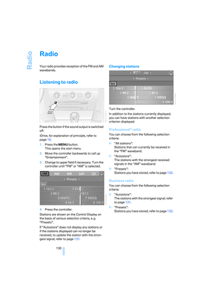 132
132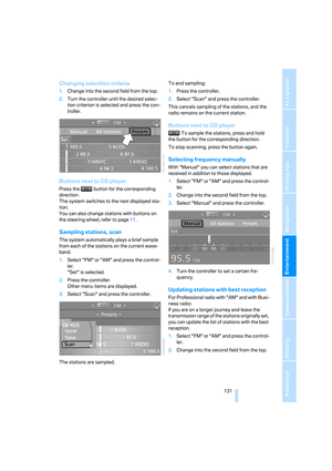 133
133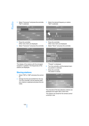 134
134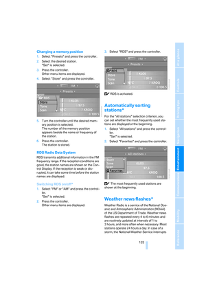 135
135 136
136 137
137 138
138 139
139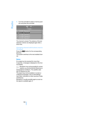 140
140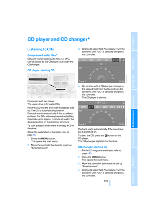 141
141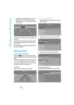 142
142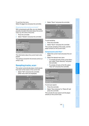 143
143 144
144 145
145 146
146 147
147 148
148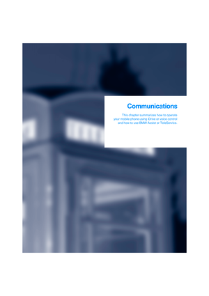 149
149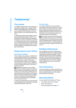 150
150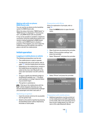 151
151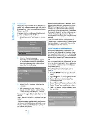 152
152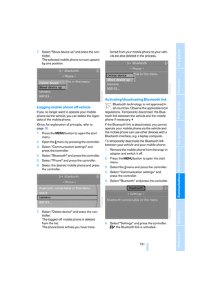 153
153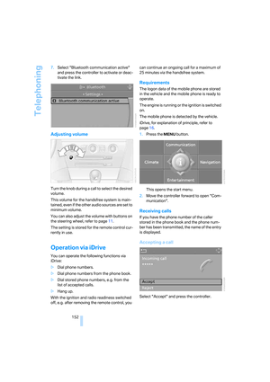 154
154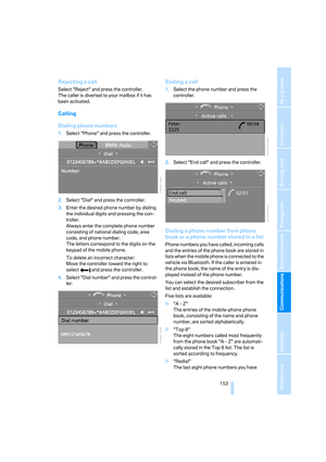 155
155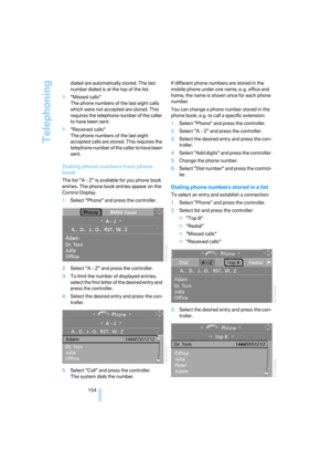 156
156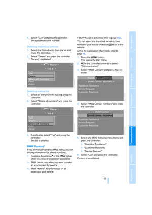 157
157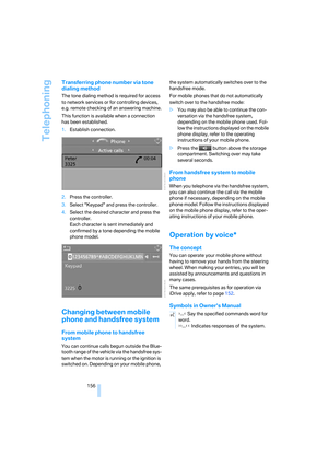 158
158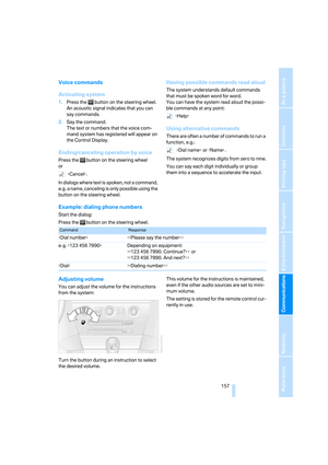 159
159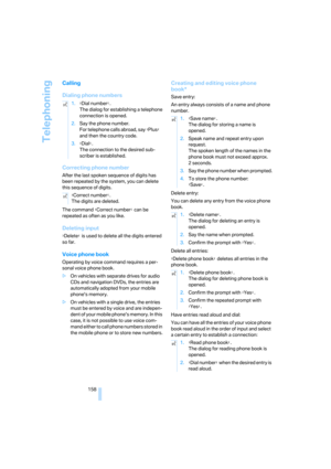 160
160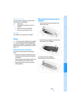 161
161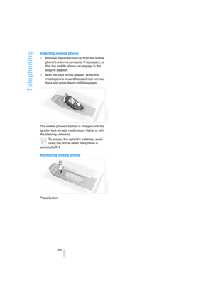 162
162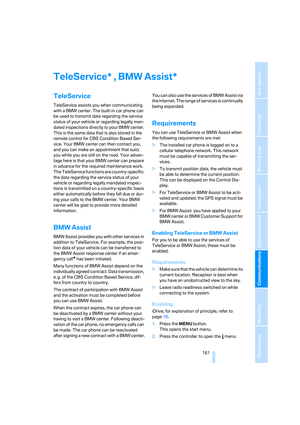 163
163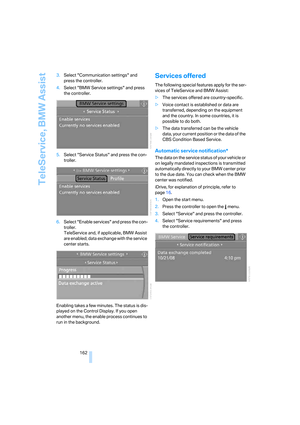 164
164 165
165 166
166 167
167 168
168 169
169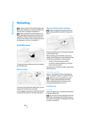 170
170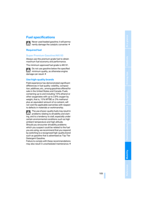 171
171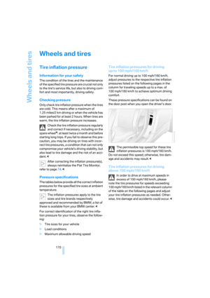 172
172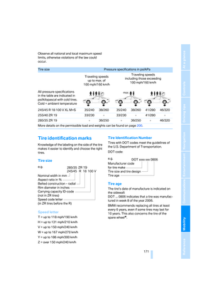 173
173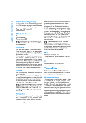 174
174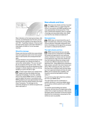 175
175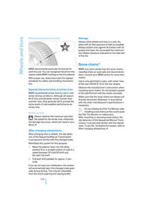 176
176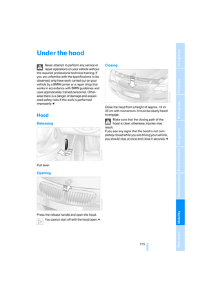 177
177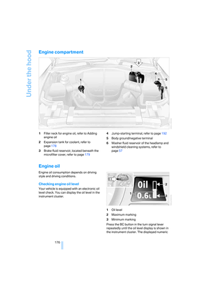 178
178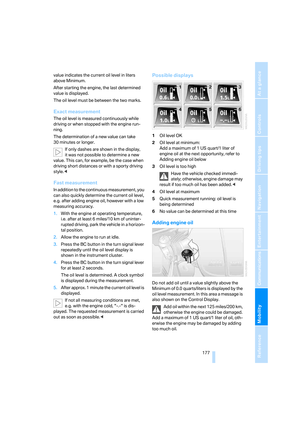 179
179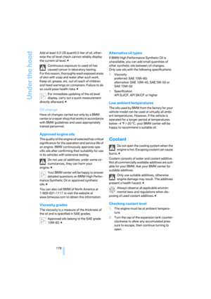 180
180 181
181 182
182 183
183 184
184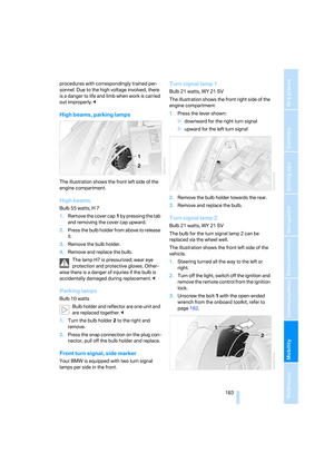 185
185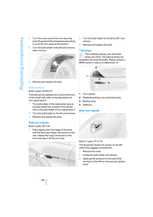 186
186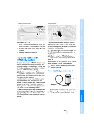 187
187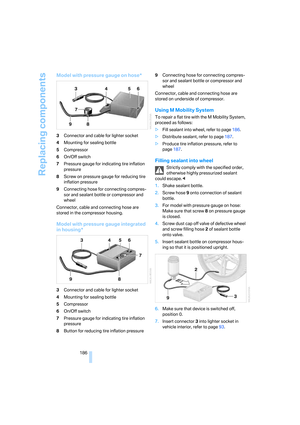 188
188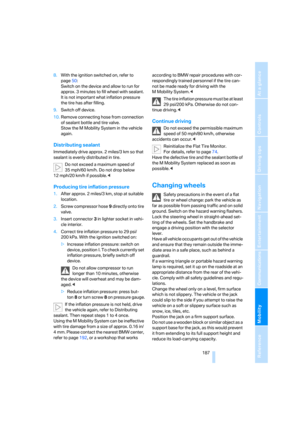 189
189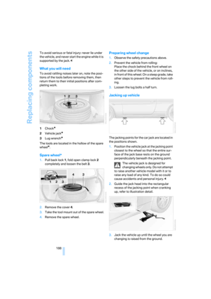 190
190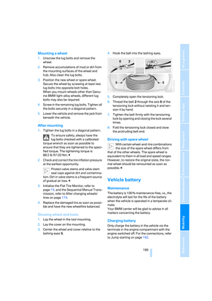 191
191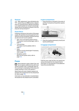 192
192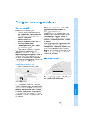 193
193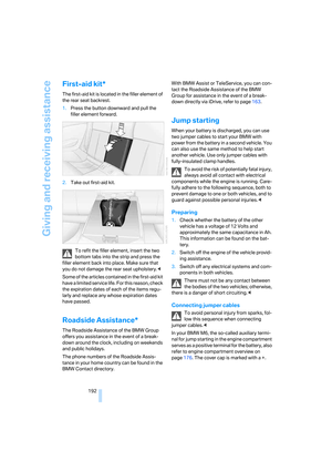 194
194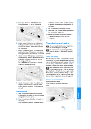 195
195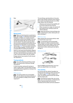 196
196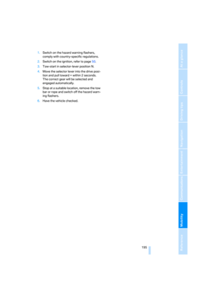 197
197 198
198 199
199 200
200 201
201 202
202 203
203 204
204 205
205 206
206 207
207 208
208 209
209 210
210 211
211 212
212 213
213 214
214 215
215 216
216 217
217 218
218 219
219 220
220 221
221 222
222 223
223 224
224 225
225 226
226