Page 49 of 79
43
TRANSMISSION OIL
GM Engines
The transaxle fill/level indicator plug for the GM engine is on the left side of the car, just behind the axle. Due to
the angle of the engine/transaxle assembly, the proper fluid level of the transaxle is about 1 in. (25.4 mm)
below the level indicator plug. The drain fitting i s identical to the fill plug and is located below the l eft axle. Both
plugs require the use of an 8mm hex wrench to remove o r install.
Honda Engines
The transaxle fill/level indicator plug for the Honda engine is on the left side of the car, just behind the axle.
Due to the angle of the engine/transaxle assembly, the proper fluid level of the transaxle is approximately
1 in. (25.4 mm) below the level indicator plug
. The drain plug is located below the left axle. Use a 17mm
wrench to remove the fill plug, and use a 3/8 in. sq uare drive to remove the drain plug.
Page 50 of 79

44
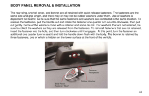
BODY PANEL REMOVAL & INSTALLATION
The rear wing, snorkel cover, and bonnet are all ret ained with quick-release fasteners. The fasteners are the
same size and grip length, and there may or may not b e rubber washers under them. Use of washers is
dependent on best fit, so be sure that the same fastener s and washers are reinstalled in the same location. To
release the fasteners, pull the handle out and rotate the fastener one quarter turn counter-clockwise, then p ull
out gently. Some of the washers come with a retainer a nd some do not. For washers that are not retained, be
sure to collect the washers as they are released from the fasteners. To reinstall fasteners that are not retained,
insert the fastener into the hole, and then turn clock wise until it engages. At this point, turn the fastener an
additional one quarter turn to seat it and fold the handle down flush with the body. The bonnet is retain ed by
three fasteners, one of which is hidden on the lower surface at the front of the vehicle.
Page 51 of 79
45
AIR FILTER REMOVAL & INSTALLATION
For vehicles with Honda engines, or GM engines with corrugated intakes, follow these directions:
To service the K&N air filter, the rear airbox cover m ust be removed. Remove the four 1/4 turn fasteners
holding the airbox cover to the engine cover and remo ve the body panel. Remove the three fasteners securing
the intake snorkel assembly, and you will find the air filter under it. The intake snorkel should rotate forward
within the roll bar to allow you access to the filter. Reverse this procedure to reinstall the air filter noti ng that the
K&N only fits in the snorkel one way.
Page 52 of 79
46
AIR FILTER REMOVAL & INSTALLATION (PLASTIC INTAKE)
If your car is equipped with a GM engine that was purch ased after November 2006, it may have a plastic intake
and require one additional step for removal.
Follow the previous instructions, and then remove the a ir filter retaining clip after the snorkel is removed. This
step will not require any tools.
NOTE: The Filtercharger® element must be cleaned and serviced with K&N cleaner and air filter oil per the
prescribed routine maintenance procedures as outlined in the product literature that accompanies the
Filtercharger®. For additional information, refer t o the K&N “Helpful Hints” document in your Owner’s Packet .
Page 53 of 79
47
SUSPENSION ADJUSTMENTS
Suspension Settings
Setting Front Rear
Ride Height 133.35 mm (5.25 in.) from lowest
part of A-arm pivot 106.35 mm (4.1875 in.) from bottom center of rear
most chassis tube under transmission Camber
-1 degree -1 degree 15 mins Toe 1 mm (.040 in.) toe out each side 1.5 mm (.059 in.) toe out each side Tire Pressure
18 PSI, 12 PSI minimum 20 PSI, 12 PSI minimum
Page 54 of 79
48
A-ARM ADJUSTMENT
A-Arm adjustments are made with the double threaded "adjustment thimbles" (see photograph) which are
located on both the front and rear upper A-arms for u se in adjusting wheel camber. The same mechanism can
be found at the rear lower A-arm for toe adjustment . The adjustment thimbles are secured with lock nuts whi ch
must be re-tightened after any adjustments are made. The vehicle must be re-aligned after any camber
adjustment is made.
Page 55 of 79
49
VEHICLE RIDE HEIGHT ADJUSTMENT
If the vehicle ride height must be adjusted, you must use the spring platform/perch on the shock body instead
of the suspension pushrod. This is also the proper method for adjusting corner weighting during suspension
set-up. Adjusting ride height with the pushrod will ne gatively affect your vehicle's suspension and bellcrank
geometry.
Page 56 of 79
50
DAMPER ADJUSTMENT
Your Ariel Atom comes with one of three damper options: (1) Rebound Adjustable, (2) Compression/Rebound
Adjustable, or (3) Compression/Rebound Dial Adjustable. Your vehicle will arrive to you with dampers set and
vehicle corner weighted from the factory. Adjusting t he suspension will require you to re-corner weight the
vehicle and should only be done for fine-tuning or pe rsonal driving preferences.


If your car is equipped with a GM engine that was purch ased after November 2006, it may have a plastic intake
and require one additi")
 from lowest
part of A-arm pivot 106.35 mm (4.1875 in.) from bottom center of rear")
 which are
located on both the front and rear upper A-arms for u se in adjust")

 Rebound Adjustable, (2) Compression/Rebound
Adjustable, or (3) Compression/Rebound Dial Adjustable. You")