Page 1193 of 2893
����
14-276A/T Gear Position Indicator
Paddle Shifter + (Upshift Switch) Replacement
A
B C
D
SRS components are")
�´
�µ
�´�µ
�´�´
�´
�µ �´
�µ
���
�(�#�'�������
���
�����
�������������
� �����)����
14-276A/T Gear Position Indicator
Paddle Shifter + (Upshift Switch) Replacement
A
B C
D
SRS components are located in this area. Review the
SRS component locations (see page 24-11) and the
precautions and procedures (see page 24-13) before
doing repair or service.1. Remove the steering wheel (see page 17-6).
2. Remove the paddle shifter (upshift switch) and the paddle shifter (downshift switch) connectors
from the connector holder, and disconnect the
connectors.
3. Remove the screws (A) securing the paddle shifter (upshift switch) and the paddle shifter
(downshift switch).
4. Remove the screws (B) securing the steering wheel rear cover (C), then remove the steering wheel rear
cover.
5. Remove the paddle shifter (upshift switch) (D) from the rear cover.
6. Install a new paddle shifter (upshift switch) in the steering wheel rear cover.
7. Install the steering wheel rear cover, and secure the rear cover with the screws.
8. Secure the paddle shifter (upshift switch) and the paddle shifter (downshift switch) with the screws. 9. Connect the paddle shifter (upshift switch) and
the paddle shifter (downshift switch) connector,
and install the connectors in the connector holder.
10. Install the steering wheel (see page 17-8).
08/08/21 14:50:02 61SNR030_140_0278
ProCarManuals.com
DYNOMITE -2009-
Page 1194 of 2893
�
��
14-277
Paddle Shifter - (Downshift Switch) Replacement
A
B C
D
SRS components are located in this area. Re")
�´
�µ
�´�µ
�µ�µ �´
�µ
�´
�µ
����
�(�#�'�������
���
�����
�������������
� �����)�
��
14-277
Paddle Shifter - (Downshift Switch) Replacement
A
B C
D
SRS components are located in this area. Review the
SRS component locations (see page 24-11) and the
precautions and procedures (see page 24-13) before
doing repair or service.
1. Remove the steering wheel (see page 17-6).
2. Remove the paddle shifter (upshift switch) and the paddle shifter (downshift switch) connectors
from the connector holder, and disconnect the
connectors.
3. Remove the screws (A) securing the paddle shifter (upshift switch) and the paddle shifter
(downshift switch).
4. Remove the screws (B) securing the steering wheel rear cover (C), then remove the steering wheel rear
cover.
5. Remove the paddle shifter (downshift switch) (D) from the rear cover.
6. Install a new paddle shifter (downshift switch) in the steering wheel rear cover.
7. Install the steering wheel rear cover, and secure the rear cover with the screws. 8. Secure the paddle shifter (upshift switch) and the
paddle shifter (downshift switch) with the screws.
9. Connect the paddle shifter (upshift switch) and the paddle shifter (downshift switch) connector,
and install the connectors in the connector holder.
10. Install the steering wheel (see page 17-8).
08/08/21 14:50:02 61SNR030_140_0279
ProCarManuals.com
DYNOMITE -2009-
Page 1296 of 2893
���
���
����
�(�#������������
��������������������� �����)����
16-416-4 Driveline/Axle
Driveshaft Inspection
Driveshaft Removal
F
D B
C
A
E A
B
1.")
���
�(�#�'�����������
���������������������"�����)���
���
����
�(�#�'�����������
��������������������� �����)����
16-416-4 Driveline/Axle
Driveshaft Inspection
Driveshaft Removal
F
D B
C
A
E A
B
1. Check the inboard boot (A) and the outboard boot (B) on the driveshaft (C) for cracks, damage, leaking
grease, and loose boot bands (D). If any damage is
found, replace the boot and the boot bands.
2. Check the driveshaft for cracks and damage. If any damage is found, replace the driveshaft.
3. Check the inboard joint (E) and the outboard joint (F) for cracks and damage. If any damage is found,
replace the inboard joint or the outboard joint as an
assembly.
4. Hold the inboard joint and turn the front wheel by hand, then make sure the joint is not excessively
loose. If necessary, replace the inboard joint or the
outboard joint as an assembly. 1. Raise the vehicle on a lift.
2. Remove the front wheels.
3. Pry up the locking tab (A) on the spindle nut (B),
then remove the nut.
4. Drain the transmission fluid, then reinstall the drain plug with a new sealing washer:
5-speed manual transmission (see page 13-5)
6-speed manual transmission (see page 13-82)
Automatic transmission (see page 14-232)
5. Remove the nuts and the bolt, then separate the lower arm using a prybar.
08/08/21 14:51:21 61SNR030_160_0004
ProCarManuals.com
DYNOMITE -2009-
Page 1313 of 2893
���� �µ�µ
�µ�µ
Grease quantity
K20Z2 engine model: 0.5 1.0 g (0.02 0.04 oz)
K20Z3 engine model: 2.0 3.0 g (0.08 0.12 oz)")
�µ
���
���� ����
�����
�(�#�'�����������
��������������������� �����)���� �µ�µ
�µ�µ
Grease quantity
K20Z2 engine model: 0.5 1.0 g (0.02 0.04 oz)
K20Z3 engine model: 2.0 3.0 g (0.08 0.12 oz)
16-20Driveline/Axle
Driveshaft Installation
(P/N 08734-0001) A
A B A
B
A
(P/N 08798-9002)
NOTE: Before starting installation, make sure the
mating surfaces of the joint and the splined section are
clean.
1. Apply about 5 g (0.18 oz) moly 60 paste (P/N 08734-0001) to the contact area (A) of the
outboard joint and the front wheel bearing.
NOTE: The paste helps to prevent noise and
vibration.
2. Install a new set ring (A) onto the set ring groove (B) of the driveshaft (left driveshaft). 3. Install a new set ring (A) onto the set ring groove
(B) of the intermediate shaft.
4. Apply super high temp urea grease (P/N 08798-9002) to the whole splined surface (A) of
the right driveshaft. After applying grease, remove
the grease from the splined grooves at intervals of
2 3 splines and from the set ring groove (B) so
that air can bleed from the intermediate shaft.
Replace.
08/08/21 14:51:31 61SNR030_160_0020
ProCarManuals.com
DYNOMITE -2009-
Page 1315 of 2893

B
A
K20Z2 engine model:
22x1.5mm
181 N·m
(18.5 kgf·m, 134 lbf·ft)
K20Z3 engine model:
24x1.5mm
245 N·m
(25.0 kgf·m, 180 lbf·ft)
9.")
�����
16-22Driveline/Axle
Driveshaft Installation (cont’d)
B
A
K20Z2 engine model:
22x1.5mm
181 N·m
(18.5 kgf·m, 134 lbf·ft)
K20Z3 engine model:
24x1.5mm
245 N·m
(25.0 kgf·m, 180 lbf·ft)
9. Apply small amount of engine oil to the seating surface of new spindle nut (A).
10. Install the spindle nut, then tighten it. After tightening, use a drift to stake the spindle nut
shoulder (B) against the driveshaft.
11. Clean the mating surfaces of the brake disc and the wheel, then install the front wheels.
12. Turn the front wheel by hand, and make sure there is no interference between the driveshaft and
surrounding parts. 13. Refill the transmission with the recommended
transmission fluid:
5-speed manual transmission (see page 13-5)
6-speed manual transmission (see page 13-82)
Automatic transmission (see page 14-232)
14. Lower the vehicle on the lift.
15. Check the wheel alignment, and adjust it if necessary (see page 18-5).
16. Test-drive the vehicle.
Replace.
Replace.
08/08/21 14:51:45 61SNR030_160_0022
ProCarManuals.com
DYNOMITE -2009-
Page 1322 of 2893
����
����
16-28Driveline/Axle
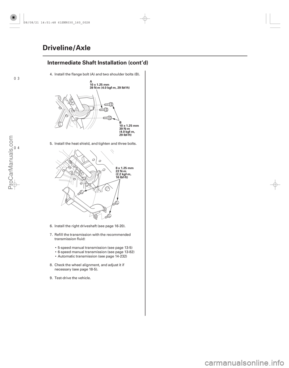
Intermediate Shaft Installation (cont’d)
A
10x1.25mm
39N·m(4.0kgf·m,29lbf·ft)
B
10x1.25mm
39 N·m
(4.0 kgf·m,
29 lbf·ft)
8x1.25mm
22 N·m
(2.2 kgf·m,
16 lbf·ft)
4. Install the flange bolt (A) and two shoulder bolts (B).
5. Install the heat shield, and tighten and three bolts.
6. Install the right driveshaft (see page 16-20).
7. Refill the transmission with the recommended transmission fluid:
5-speed manual transmission (see page 13-5)
6-speed manual transmission (see page 13-82)
Automatic transmission (see page 14-232)
8. Check the wheel alignment, and adjust it if necessary (see page 18-5).
9. Test-drive the vehicle.
08/08/21 14:51:48 61SNR030_160_0028
ProCarManuals.com
DYNOMITE -2009-
Page 1324 of 2893
����
Steering
Steering
EPS (Electrical Power Steering) Components
........................................................................................")
�(�#�'�������������������������
�����
�/�����)����
Steering
Steering
EPS (Electrical Power Steering) Components
..............................................................................................................................
..................................................... ................
............................................ ...............
........................................ .................................
.......................................
........................................
.............................................. .................
.....................
................................................................
..............................................................
..................................................... ................
............................................ ...............
........................................ .................................
.......................................
........................................
.............................................. .................
.....................
Special Tools
. 17-2
Component Location Index . 17-3
Steering Wheel Rotational Play Check . 17-4
Power Assist Check . 17-4
Steering Linkage and Gearbox Inspection . 17-5
Steering Wheel Removal . 17-6
Steering Wheel Disassembly/Reassembly . 17-7
Steering Wheel Installation . 17-8
Column Cover Removal and Installation . 17-9
Steering Column Removal and Installation . 17-10
Steering Column Inspection . 17-14
Steering Lock Replacement . 17-14
Rack Guide Adjustment . 17-15
Tie-rod End Ball Joint Boot Replacement . 17-16
Gearbox Mount Cushion Replacement . 17-17
........................................ ...........................
....................................... ..............................
.....................................................
............................................................ .......................................................................................... ......................................
...........................
............................... ......................
........................................
...........................
....................................... ..............................
.....................................................
............................................................ .......................................................................................... ......................................
...........................
............................... ......................
Component Location Index
. 17-18
General Troubleshooting Information . 17-19
Memorizing the Torque Sensor Neutral Position . 17-22
DTC Troubleshooting Index . 17-23
Symptom Troubleshooting Index . 17-25
System Description . 17-26
Circuit Diagram . 17-30
DTC Troubleshooting . 17-33
Symptom Troubleshooting . 17-60
EPS Motor Removal and Installation . 17-63
Steering Gearbox Removal and Installation . 17-65
Rack End Removal and Installation . 17-79
Rack Guide Removal/Installation . 17-83
EPS Control Unit Removal/Installation . 17-84
08/08/21 14:53:09 61SNR030_170_0002
ProCarManuals.com
DYNOMITE -2009-
Page 1326 of 2893
����
�(�#�'���������������������������������������)����
17-3
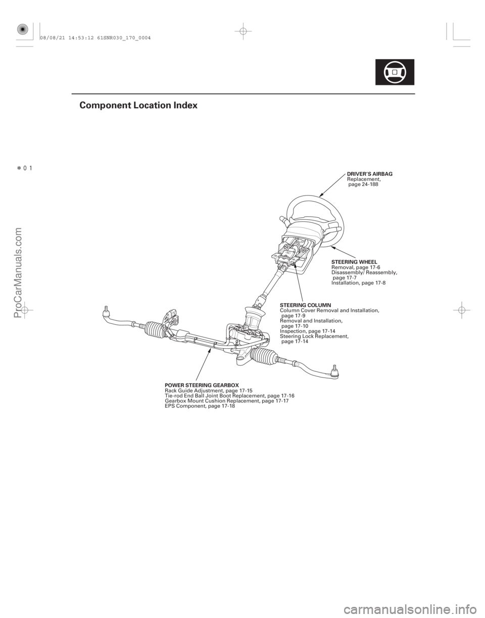
Component Location Index
DRIVER’S AIRBAG
POWER STEERING GEARBOX STEERING COLUMN
STEERING WHEELReplacement,
page 24-188
Rack Guide Adjustment, page 17-15
Tie-rod End Ball Joint Boot Replacement, page 17-16
Gearbox Mount Cushion Replacement, page 17-17
EPS Component, page 17-18 Column Cover Removal and Installation,
page 17-9
Removal and Installation, page 17-10
Inspection, page 17-14
Steering Lock Replacement, page 17-14 Removal, page 17-6
Disassembly/ Reassembly,
page 17-7
Installation, page 17-8
08/08/21 14:53:12 61SNR030_170_0004
ProCarManuals.com
DYNOMITE -2009-