Page 1178 of 2893
�
��
14-262Automatic Transmission
Shift Cable Adjustment (cont’d)
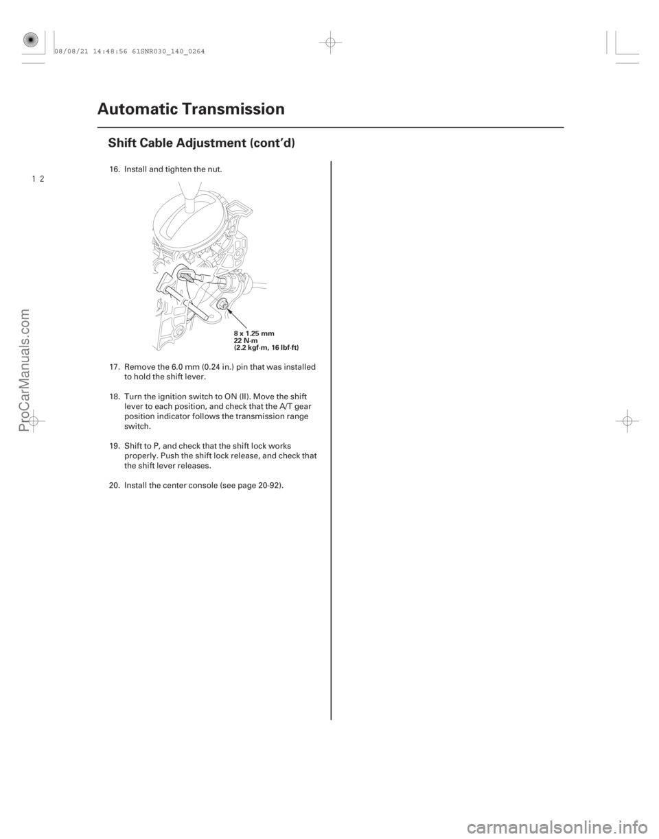
8x1.25mm
22 N·m
(2.2 kgf·m, 16 lbf·ft)
16. Install and tighten the nut.
17. Remove the 6.0 mm (0.24 in.) pin that was installed
to hold the shift lever.
18. Turn the ignition switch to ON (II). Move the shift lever to each position, and check that the A/T gear
position indicator follows the transmission range
switch.
19. Shift to P, and check that the shift lock works properly. Push the shift lock release, and check that
the shift lever releases.
20. Install the center console (see page 20-92).
08/08/21 14:48:56 61SNR030_140_0264
ProCarManuals.com
DYNOMITE -2009-
Page 1180 of 2893
����
�Ó
�Ú
�Ø �´
�µ �µ
14-264
A/T Gear Position Indicator
Circuit Diagram
22
36 444342 27 28 30 33 34 35
3225
20 21 22 16 1817
13 14 15
1211")
����
�(�#�'�������
���
�����
���������������������)����
�Ó
�Ú
�Ø �´
�µ �µ
14-264
A/T Gear Position Indicator
Circuit Diagram
22
36 444342 27 28 30 33 34 35
3225
20 21 22 16 1817
13 14 15
1211 789
3
1
3123
31
456
1514
21
20 25
24
34
33
292827
42 44
40
37
36 31
1
23456 9 87
11 12 151413 17 1816
32
29 30
42 43 44
40
39
36
18
17
16 19
3598
10 21
20
27
2
26 29 40
4
23 24
41 23
41
10
26
39
5 6
2
1
1 2
CABLE REEL
BLU
BLU
BLU/YEL
GRN
GRN
SUPP B16
B40
SDNP
BRN
PG1
PG2
LG1
LG2
C40 B1
C44 B36
BLK
BRN/YEL
BRN/YEL
G101 No. 14 (7. 5 A)
RED GRY
2
1
RED/BLK RED
PG SG16
15
BLK BRN
C(44P)
B (44P)
A(44P)
Terminal side of female terminals
19 1
WHT
RED RED
WHT
17
CANL
A37 A36 CANH
1
3827
64 1017
54938 10
BLK
B13 BLK/GRN
BRN
C36
IG1
12 V
GAUGE CONTROL MODULE (TACH) No. 2 (15 A)
UNDER-DASH FUSE/RELAY BOX
No. 10 (7. 5 A)
BLU/WHT
RED/BLK
WHT ORN
BAT
IG1
IGNITION SWITCH
BLK
BLU/WHT
FWD RVS
S ST
P R
N
TRANSMISSION RANGE SWITCH D
B22
ATPRVS
ATPFWD
ATPP
ATPR ATPN ATPD ATPS
YEL/RED
B28
G101
B12
B21
BLU
PNK
RED/BLK
WHT
BLK/BLU
B14 B15
WHT/RED
BLU/BLK YEL/GRN
RED
BLU/YEL
BLK
G503
D N
R
P
UNDER-HOOD FUSE/RELAY BOX
No. 2 (IG) (50 A)
No. 1 (100 A)
BATTERY
A/T
GEAR
POSITION
INDICATOR
DRIVER
CIRCUIT
CPU STARTER
CUT RELAY
POWERTRAIN CONTROL
MODULE (PCM)
F-CAN
TRANSCEIVER
DASH-LIGHT
BRIGHTNESS
CONTROL
CIRCUIT
A/T GEAR
POSITION
INDICATOR
PANEL LIGHT
MULTIPLEX INTEGRATED
CONTROL UNIT (MICU)
MULTIPLEX INTEGRATED
CONTROL UNIT (MICU)
SHIFT
INDICATOR
LT GRNLEFT
BLK/WHT LT GRN GRN/ORN
RIGHT
PADDLE SHIFTER
(UPSHIFT SWITCH)
RED/WHT
G504 G504
5V
BLK*
BLK/RED*
BLK16
17
6 16
17
7
PADDLE SHIFTER
(DOWNSHIFT SWITCH)*1: ’06 model
*2: ’07 09 models
PCM Connector Terminal Locations
S
GND
21
08/08/21 14:49:00 61SNR030_140_0266
ProCarManuals.com
DYNOMITE -2009-
Page 1184 of 2893

A
C
B
6x1.0mm
12 N·m (1.2 kgf·m, 8.7 lbf·ft) 6x1.0mm
12 N·m (1.2 kgf·m, 8.7 lbf·ft)A
7. Install t")
����
��������
14-268A/T Gear Position Indicator
Transmission Range Switch Replacement (cont’d)
A
C
B
6x1.0mm
12 N·m (1.2 kgf·m, 8.7 lbf·ft) 6x1.0mm
12 N·m (1.2 kgf·m, 8.7 lbf·ft)A
7. Install the transmission range switch (A) gently on
the selector control shaft (B) while holding it in the
N position with the 2.0 mm (0.08 in.) blade (C).
8. Tighten the bolts on the transmission range switch while you continue to holding the N position. Do
not move the transmission range switch when
tightening the bolts. Remove the feeler gauge. 9. Check the connectors for rust, dirt, or oil, clean or
repair if necessary, then connect the connector
securely.
10. Turn the ignition switch to ON (II). Move the shift lever through all positions, and check the
transmission range switch synchronization with the
A/T gear position indicator.
11. Check that the engine will start with the shift lever in P and N, and will not start in any other shift lever
position.
12. Check that the back-up lights come on when the shift lever is in R.
13. Allow the front wheels to rotate freely, then start the engine, and check the shift lever operation.
14. Install the transmission range switch cover (A).
08/08/21 14:49:03 61SNR030_140_0270
ProCarManuals.com
DYNOMITE -2009-
Page 1188 of 2893
�´
��������
�µ
�µ�µ �µ
YES
NO YES
NO
14-271
SUPP (BLU)
CABLE REEL 20P CONNECTOR
SUPP (BLU)
CABLE REEL 20P CONNECTOR
GND (BLK)
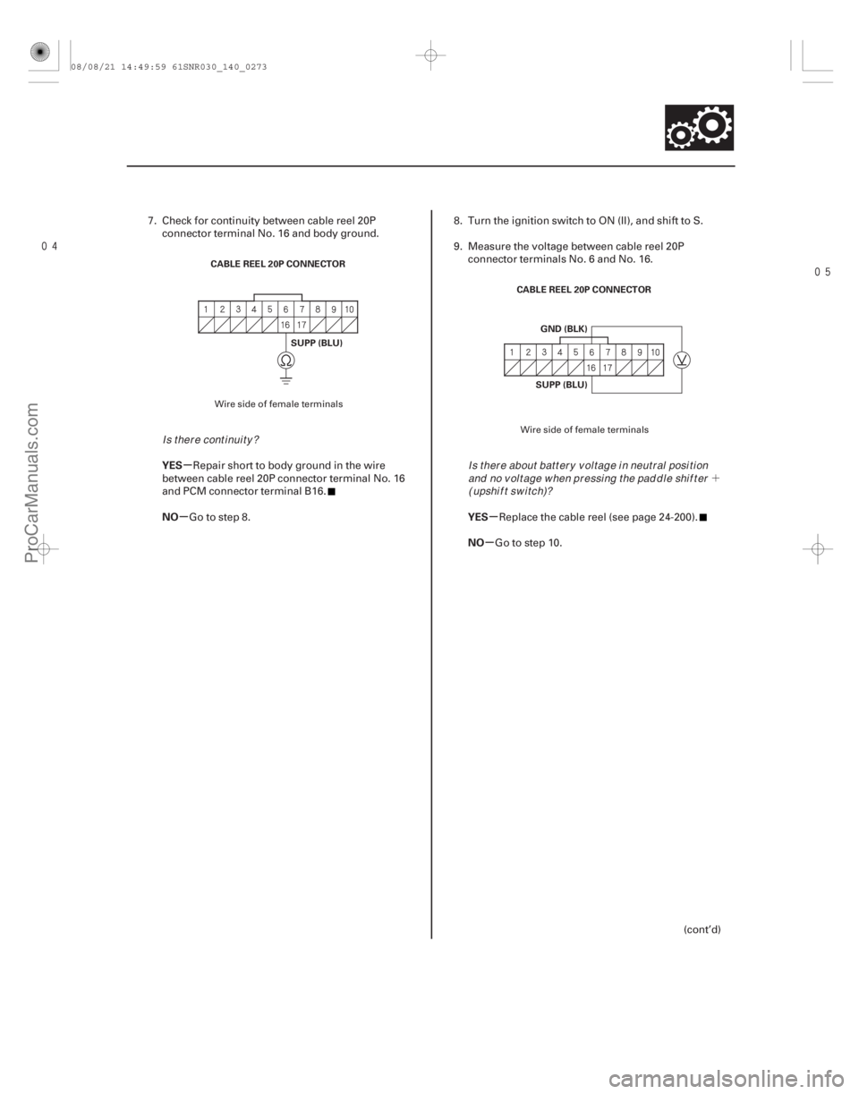
7. Check for continuity between cable reel 20Pconnector terminal No. 16 and body ground.
Repair short to body ground in the wire
between cable reel 20P connector terminal No. 16
and PCM connector terminal B16.
Go to step 8. 8. Turn the ignition switch to ON (II), and shift to S.
9. Measure the voltage between cable reel 20P
connector terminals No. 6 and No. 16.
Replace the cable reel (see page 24-200).
Go to step 10.
(cont’d)
Wire side of female terminals Wire side of female terminals
Is there continuity?Is t her e about bat t er y v ol t age i n neut r al posi t i onand no v ol t age w hen pr essi ng t he pad d l e shi f t er(upshift switch)?
08/08/21 14:49:59 61SNR030_140_0273
ProCarManuals.com
DYNOMITE -2009-
Page 1189 of 2893
 Circuit Troubleshooting (cont’d)
CABLE REEL 20P CONNECTOR
SUPP (BLU)
JUMPER WIRE PCM CONNECTOR B (4")
����������
�µ
�µ
YES
NO
14-272 A/T Gear Position Indicator
Paddle Shifter + (Upshift Switch) Circuit Troubleshooting (cont’d)
CABLE REEL 20P CONNECTOR
SUPP (BLU)
JUMPER WIRE PCM CONNECTOR B (44P)
SUPP (BLU/YEL)
10. Turn the ignition switch to LOCK (0).
11. Jump the SCS line with the HDS.
12. Disconnect PCM connector B (44P).
13. Connect cable reel 20P connector terminal No. 16 and body ground with a jumper wire. 14. Check for continuity between PCM connector
terminal B16 and body ground.
Check for poor connections or loose
terminals between cable reel 20P connector
terminal No. 16 and PCM connector terminal B16. If
the connection is OK, update the PCM if it does not
have the latest software (see page 11-227), or
substitute a known-good PCM (see page 11-7), then
recheck. If the symptom goes away with a known-
good PCM, replace the original PCM (see page
11-228).
Repair open in the wire between PCM
connector terminal B16 and the cable reel 20P
connector.
Wire side of female terminals Terminal side of female terminals
Is there continuity?
08/08/21 14:50:00 61SNR030_140_0274
ProCarManuals.com
DYNOMITE -2009-
Page 1191 of 2893
�µ
�
���
�
�µ
�µ �µ
�µ
YES
NO
YES
NO
14-274A/T Gear Position Indicator
Paddle Shifter - (Downshift Switch) Circuit Troubleshooting (cont’d)
SDNP (GRN)
CABLE REEL 20P CONNECTOR
SDNP (GRN)
CABLE REEL 20P CONNECTOR
GND (BLK)
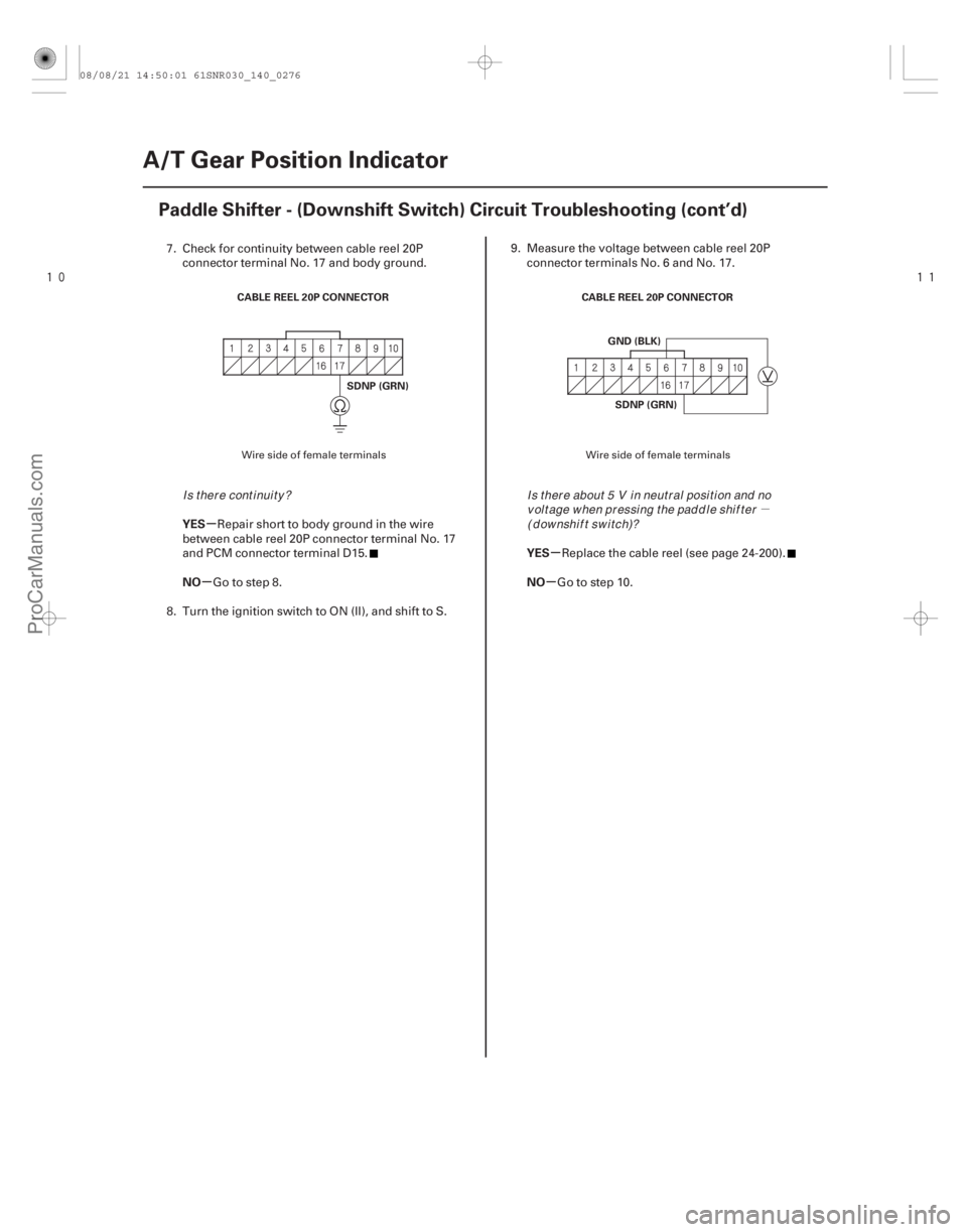
7. Check for continuity between cable reel 20Pconnector terminal No. 17 and body ground.
Repair short to body ground in the wire
between cable reel 20P connector terminal No. 17
and PCM connector terminal D15.
Go to step 8.
8. Turn the ignition switch to ON (II), and shift to S. 9. Measure the voltage between cable reel 20P
connector terminals No. 6 and No. 17.
Replace the cable reel (see page 24-200).
Go to step 10.
Wire side of female terminals Wire side of female terminals
I s t her e cont i nui t y ?I s t her e about 5 V i n neut r al posi t i on and no
v ol t age w hen pr essi ng t he pad d l e shi f t er( d ow nshi f t sw i t ch)?
08/08/21 14:50:01 61SNR030_140_0276
ProCarManuals.com
DYNOMITE -2009-
Page 1192 of 2893

JUMPER WIRE PCM CONNECTOR B (44P)
SDNP (BRN)
10. Turn the ignition switch to LOCK (0).
11. Jump the SCS line with the HDS.
12.")
����������
�µ
�µ
YES
NO
14-275
CABLE REEL 20P CONNECTOR
SDNP (GRN)
JUMPER WIRE PCM CONNECTOR B (44P)
SDNP (BRN)
10. Turn the ignition switch to LOCK (0).
11. Jump the SCS line with the HDS.
12. Disconnect PCM connector B (44P).
13. Connect cable reel 20P connector terminal No. 17and body ground with a jumper wire. 14. Check for continuity between PCM connector
terminal B40 and body ground.
Check for poor connections or loose
terminals between cable reel 20P connector
terminal No. 17 and PCM connector terminal B40. If
the connection is OK, update the PCM if it does not
have the latest software (see page 11-227), or
subsitute a known-good PCM (see page 11-7), then
recheck. If the symptom goes away with a known-
good PCM, replace the original PCM (see page
11-228).
Repair open in the wire between PCM
connector terminal B40 and the cable reel 20P
connector.
Wire side of female terminals Terminal side of female terminals
Is there continuity?
08/08/21 14:50:01 61SNR030_140_0277
ProCarManuals.com
DYNOMITE -2009-
Page 1196 of 2893
����
�Ó
�Ú
�Ø �µ
14-279
Circuit Diagram
22
36 444342 27 28
3033 34 35
32 25
20 21 22 16 1817
13 14 15
12
11 789
31
3123
31
456
1514
2120 25
24")
����
�(�#�'�������
���
���������������������������)����
�Ó
�Ú
�Ø �µ
14-279
Circuit Diagram
22
36 444342 27 28
3033 34 35
32 25
20 21 22 16 1817
13 14 15
12
11 789
31
3123
31
456
1514
2120 25
24
34
33
292827
42 44
40
37
36 31
123456 9
87
11 12 151413 17 1816
32
29
30
42 43 44
40
39
36
18
17
16 19
3598
10 2120
27
2
26 29 40
4
23 24
41 23
41
39
10
26
G601
4 3
DN
R
P ST
S RVS
FWD
BKSW LT GRN
LT GRNWHT
No. 12 (15 A)
YEL
BRN
PG SG 16
15
BLK A40
BKSW
WHT/BLK BLK LT BLU
BLK
C(44P)
B(44P)
A(44P)
Terminal side of female terminals
G503
BLK A36
A37
WHT
RED
RED
WHT
1
19 CANH
CANL
17
P
R
N
D
S
GAUGE CONTROL MODULE (TACH)
2 1 3 4 1
3827
65 41017
6
549 38 10
KEYSW KEYSOL
G504
BLU
PNK
PUR
BLK P-PIN
ATPPBLU/BLK 5 4 6 2 1
3
GRY PUR
LT BLU
A24
VCC5
APSB A18
A34
SG5
SG4
A35
A17
APSA VCC4 A25
BLUYEL
BRN
PG1
PG2
LG1
LG2
C40 B1
C44 B36
BRN/YEL
BRN/YEL
G101 PNK
BLK
B13 BLK/GRN
BRN
C36
IG1
12 V
No. 2 (15 A)
UNDER-DASH FUSE/RELAY BOX
No. 10 (7. 5 A)
BLU/WHT
RED/BLK
WHT ORN
SLS
A27
RED
BLK BAT
IG1
IGNITION SWITCH
5V
BLK
BLU/WHT
TRANSMISSION RANGE SWITCH
B22
ATPRVS
ATPFWD
ATPP
ATPR ATPN ATPD
ATPS
YEL/RED
B28
G101
B12
B21
BLU
PNK
RED/BLK
WHT
BLK/BLU
B14 B15
WHT/RED
BLU/BLK YEL/GRN
RED
BLU/YEL
1
2 YEL
PNK
UNDER-HOOD FUSE/RELAY BOX
No. 2 (IG) (50 A)
No. 1 (100 A)
BATTERY
STARTER
CUT
RELAY
SHIFT
LOCK
SOLENOID BRAKE
PEDAL
POSITION
SWITCH
ACCELERATOR
PEDAL
POSITION
SENSOR
KEY
INTERLOCK
SOLENOID IGNITION
KEY
SWITCH UNDER-DASH
FUSE/RELAY BOX
No.35(7.5A)
F-CAN
TRANSCEIVER
CPU A/T
GEAR
POSITION
INDICATOR
DRIVER
CIRCUIT
PARK PIN
SWITCH DASH-LIGHT
BRIGHTNESS
CONTROL
CIRCUIT
POWERTRAIN CONTROL
MODULE (PCM)
MULTIPLEX
INTEGRATED
CONTROL
UNIT (MICU)
SHIFT
INDICATOR
RED/WHT
GRN
G504
BLK/RED* BLK* *1: ’06 model
*2: ’07 09 models
BLK PCM Connector Terminal Locations GND
1
2
08/08/21 14:50:06 61SNR030_140_0281
ProCarManuals.com
DYNOMITE -2009-