Page 440 of 2893

07406-0070301
B
07NAJ-P07010A
07ZAJ-S5AA200
19. Turn the ign")
���
�µ
�µ �µ
�µ
�µ
�µ
YES
NO YES
NO
YES
NO
11-117
07406-0020201 or
07MAJ-PY4011A and
07MAJ-PY40120
A
22 N·m
(2.2 kgf·m,
16 lbf·ft)
07406-0070301
B
07NAJ-P07010A
07ZAJ-S5AA200
19. Turn the ignition switch to LOCK (0).
20. Remove the cowl cover and the under cowl panel (see page 20-163).
21. Remove the rocker arm oil pressure switch (A), and attach the special tools as shown, then attach the
rocker arm oil pressure switch to the pressure
gauge attachment (B).
NOTE: Install the parts in the reverse order of
removal with a new O-ring.
22. Reconnect the rocker arm oil pressure switch 2P connector.
23. Start the engine. Hold the engine speed at 3,000 rpm without load (A/T in P or N, M/T in
neutral) until the radiator fan comes on, then let it
idle.
24. Check the oil pressure at engine speeds of 1,000 rpm and 2,000 rpm.
Check for air in the fuel line, then go to step
25.
Inspect the VTEC system, then go to step 25. 25. Turn the ignition switch to ON (II).
26. Reset the ECM/PCM with the HDS.
27. Clear the CKP pattern with the HDS.
28. Do the ECM/PCM idle learn procedure (see page
11-310).
29. Do the CKP pattern learn procedure (see page 11-4).
30. Test-drive the vehicle for several minutes in the range of these recorded freeze data parameters:
ENGINE S PEED
VSS
REL TP SENSOR
CLV (calculated load value)
APP SENSOR
31. Check for Temporary DTCs or DTCs with the HDS.
Check for poor connections or loose
terminals at the ignition coil(s), the injector(s), and
the ECM/PCM, then go to troubleshooting DTC
P0301, P0302, P0303, or P0304 (see page 11-118).
Go to step 32.
32. Monitor the OBD STATUS for DTC P0301, P0302, P0303, or P0304 in the DTCs MENU with the HDS.
Troubleshooting is complete. If any other
Temporary DTCs or DTCs were indicated in step 31,
go to the indicated DTC’s troubleshooting.
If the screen indicates FAILED, go to step 1
and recheck. If the screen indicates EXECUTING,
keep driving until a result comes on. If the screen
indicates OUT OF CONDITION, go to step 30.
Is t he oi l pr essur e bel ow 49 k Pa ( 0.5 k gf / cm , 7psi)? Is DT C P0300, P0301, P0302, P0303, or P0304
indicated?
Does t he scr een i nd i cat e PASSE D?2
08/08/21 14:17:25 61SNR030_110_0117
ProCarManuals.com
DYNOMITE -2009-
Page 542 of 2893
���
�(�#�'��������������������������������� �����)����
11-219
Injector Replacement
A BC
D
E
F
1. Relieve fuel pressure (see page 11-322).
2. Remove the engine cover.
3. Disconnect the injector connectors (A) from the injectors.
4. Remove the ground cable bolt (G101) (B).
5. Disconnect the quick-connect fitting (C).
6. Remove the fuel rail mounting nuts (D) from the fuel rail (E).
7. Remove the fuel rail and the injectors from the injector base.
8. Remove the injector clips (F) from the injectors.
9. Remove the injectors from the fuel rail.
(cont’d)
* : This illustration shows K20Z2 engine
08/08/21 14:23:35 61SNR030_110_0219
ProCarManuals.com
DYNOMITE -2009-
Page 639 of 2893
����
�(�#�'���������������������������������������)����
11-311
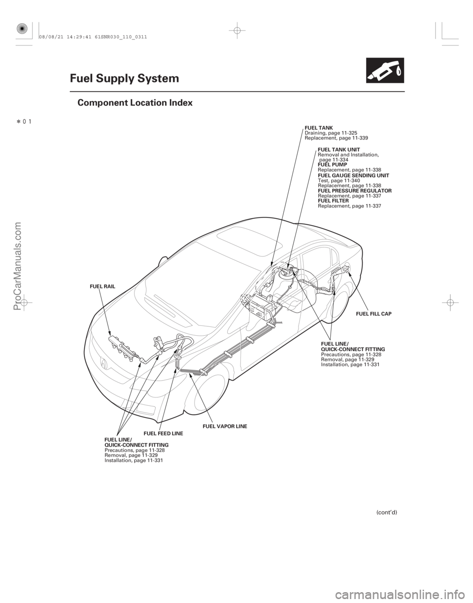
Fuel Supply System
Component Location Index
FUEL FEED LINE
FUEL VAPOR LINE
FUEL RAIL
QUICK-CONNECT FITTING QUICK-CONNECT FITTING
FUEL FILL CAP
FUEL TANK
FUEL PUMPFUEL GAUGE SENDING UNIT
FUEL PRESSURE REGULATOR
FUEL FILTER
FUEL TANK UNIT
FUEL LINE/
FUEL LINE/
(cont’d)
Precautions, page 11-328
Removal, page 11-329
Installation, page 11-331 Precautions, page 11-328
Removal, page 11-329
Installation, page 11-331
Draining, page 11-325
Replacement, page 11-339
Replacement, page 11-338Test, page 11-340
Replacement, page 11-338Replacement, page 11-337
Replacement, page 11-337
Removal and Installation,
page 11-334
08/08/21 14:29:41 61SNR030_110_0311
ProCarManuals.com
DYNOMITE -2009-
Page 650 of 2893
���
With the HDS
11-322 Fuel Supply System
Fuel Pressure Relieving
A
A
A
Before disconnecting fuel lines or hoses, relieve
pressure from th")
���
����
����
�(�#�'���������������������������������"�����)���
With the HDS
11-322 Fuel Supply System
Fuel Pressure Relieving
A
A
A
Before disconnecting fuel lines or hoses, relieve
pressure from the system by disabling the fuel pump
and then disconnecting the fuel tube/quick connect
fitting in the engine compartment. 1. Turn the ignition switch to LOCK (0).
2. Connect the HDS to the data link connector (DLC) (A) located under the driver’s side of the dashboard.
3. Turn the ignition switch to ON (II).
4. Make sure the HDS communicates with the ECM/ PCM. If it doesn’t, go to the DLC circuit
troubleshooting (see page 11- 204).
5. Turn the ignition switch to LOCK (0).
6. Remove the fuel fill cap to relieve the pressure in the fuel tank.
7. Turn the ignition switch to ON (II).
8. From the INSPECTION MENU of the HDS, select Fuel Pump OFF, then start the engine, and let it idle
until it stalls.
NOTE: Do not allow the engine to idle above 1,000 rpm or the ECM/PCM will continue to operate the fuel
pump.
A DTC or a Temporary DTC may be set during this procedure. Check for DTCs, and clear them
as needed (see page 11-4). 9. Turn the ignition switch to LOCK (0).
10. Do the battery terminal disconnection procedure (see page 22-68).
11. Remove the quick-connect fitting cover (A).
12. Check the fuel quick-connect fitting for dirt, and clean it if needed.
13. Place a rag or shop towel over the quick-connect fitting (A).
08/08/21 14:29:48 61SNR030_110_0322
ProCarManuals.com
DYNOMITE -2009-
Page 652 of 2893

A
A A
B C
E
D
7. Remove the quick-connect fitting cover (A).
8. Check the fuel quick-connect fitting for dirt, and
clean it if")
����
��������
11-324Fuel Supply System
Fuel Pressure Relieving (cont’d)
A
A A
B C
E
D
7. Remove the quick-connect fitting cover (A).
8. Check the fuel quick-connect fitting for dirt, and
clean it if needed.
9. Place a rag or shop towel over the quick-connect fitting (A). 10. Disconnect the quick-connect fitting (A): Hold the
connector (B) with one hand, and squeeze the
retainer tabs (C) with the other hand to release
them from the locking tabs (D). Pull the connector
off.
NOTE: Be careful not to damage the line (E) or other parts.
Do not use tools.
If the connector does not move, keep the retainer tabs pressed down, and alternately pull and push
the connector until it comes off easily.
Do not remove the retainer from the line; once removed, the retainer must be replaced with a
new one.
11. After disconnecting the quick-connect fitting, check it for dirt or damage (see step 4 on page 11-330).
12. Do the battery terminal reconnection procedure (see page 22-68).
08/08/21 14:29:49 61SNR030_110_0324
ProCarManuals.com
DYNOMITE -2009-
Page 653 of 2893
���� �(�#��������������������������������
�!�����)�
�� Special Tools Required
11-32511-325
Fuel Pressure Test Fuel Tank Draining
07406-00")
�µ�µ �µ
���
�(�#�'���������������������������������������)���� �(�#�'�������������������������������
�!�����)�
�� Special Tools Required
11-32511-325
Fuel Pressure Test Fuel Tank Draining
07406-004000B
07AAJ-S6MA150
Fuel pressure gauge 07406-004000B
Fuel pressure gauge attachment set 07AAJ-S6MA150 1. Relieve the fuel pressure (see page 11-322).
2. Disconnect the quick-connect fitting. Attach the fuel pressure gauge set and the fuel pressure gauge.
3. Start the engine, and let it idle. If the engine starts, go to step 5.
If the engine does not start, go to step 4.
4. Check to see if the fuel pump is running: Listen to the fuel filler port with the fuel fill cap removed.
The fuel pump should run for 2 seconds when the
ignition switch is first turned on.
If the pump runs, go to step 5.
If the pump does not run, do the fuel pump circuit troubleshooting (see page 11- 318).
5. Read the fuel pressure gauge. The pressure should be 330 380 kPa (3.4 3.9 kgf/cm , 48 55 psi).
If the pressure is OK, the test is complete.
If the pressure is out of specification, replace the fuel pressure regulator (see page 11-337) and the
fuel filter (see page 11-337), then recheck the fuel
pressure. 1. Remove the fuel tank unit (see page 11-334).
2. Using a hand pump, a hose, and a container
suitable for fuel, draw the fuel from the fuel tank.
3. Reinstall the fuel tank unit (see page 11-335).
2
08/08/21 14:29:49 61SNR030_110_0325
ProCarManuals.com
DYNOMITE -2009-
Page 657 of 2893
����
11-329
Fuel Line/Quick-Connect Fitting Removal
A
AA
A AA
A B
D
C
NOTE: Before you work on the fuel lines and fittings,
read t")
���
����
��������
����
�(�#�'�������������������������������
� �����)����
11-329
Fuel Line/Quick-Connect Fitting Removal
A
AA
A AA
A B
D
C
NOTE: Before you work on the fuel lines and fittings,
read the Fuel Line/Quick-Connect Fitting Precautions
(see page 11-328).
1. Relieve the fuel pressure (see page 11-322).
2. Check the fuel quick-connect fittings (A) for dirt, and clean them if needed.
3. Place a rag or shop towel over the quick-connectfitting. Hold the connector (A) with one hand, and
squeeze the retainer tabs (B) with the other hand to
release them from the locking tabs (C). Pull the
connector off.
NOTE: Be careful not to damage the line (D) or other parts.
Do not use tools.
If the connector does not move, keep the retainer tabs pressed down, and alternately pull and push
the connector until it comes off easily.
Do not remove the retainer from the line; once removed, the retainer must be replaced with a
new one.
(cont’d)
* : This illustration shows K20Z2 engine.
08/08/21 14:29:53 61SNR030_110_0329
ProCarManuals.com
DYNOMITE -2009-
Page 661 of 2893
���
����Connection to new fuel line
11-333
A
B
Sanoh-made Tokai-made
A
B C
5. When you reconnect the connector with the old
retainer, make sure the connection is secure and
the tabs (A) are firmly locked into place; check
visually and also by pulling the connector (B).
When you replace the fuel line with a new one,
make sure you remove the ring pull (C) upwards
after you confirm the connection is secure.
NOTE: Before you remove the ring pull, make sure
the fuel line connection is secure. If the connection
is not secure, the ring pull could break when you try
to remove it. 6. Reconnect the negative cable to the battery, and
turn the ignition switch to ON (II) (but do not
operate the starter motor). The fuel pump will run
for about 2 seconds, and fuel pressure will rise.
Repeat this two or three times, then check that
there is no leakage in the fuel supply system.
08/08/21 14:30:57 61SNR030_110_0333
ProCarManuals.com
DYNOMITE -2009-