Page 1523 of 2893

����
19-31
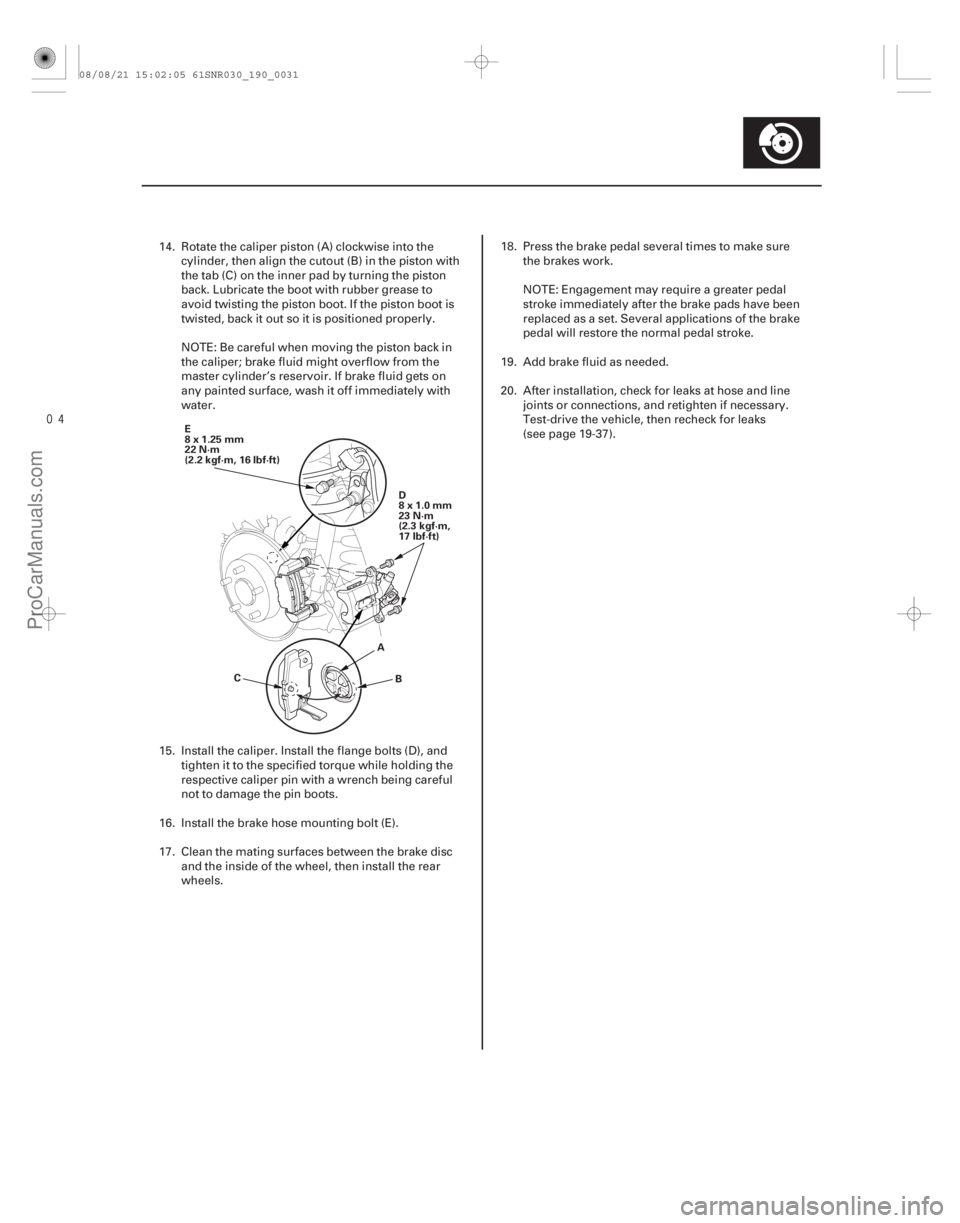
E
8x1.25mm
22 N·m
(2.2 kgf·m, 16 lbf·ft)D
8x1.0mm
23 N·m
(2.3 kgf·m,
17 lbf·ft)
A B
C
14. Rotate the caliper piston (A) clockwise into the
cylinder, then align the cutout (B) in the piston with
the tab (C) on the inner pad by turning the piston
back. Lubricate the boot with rubber grease to
avoid twisting the piston boot. If the piston boot is
twisted, back it out so it is positioned properly.
NOTE: Be careful when moving the piston back in
the caliper; brake fluid might overflow from the
master cylinder’s reservoir. If brake fluid gets on
any painted surface, wash it off immediately with
water.
15. Install the caliper. Install the flange bolts (D), and tighten it to the specified torque while holding the
respective caliper pin with a wrench being careful
not to damage the pin boots.
16. Install the brake hose mounting bolt (E).
17. Clean the mating surfaces between the brake disc and the inside of the wheel, then install the rear
wheels. 18. Press the brake pedal several times to make sure
the brakes work.
NOTE: Engagement may require a greater pedal
stroke immediately after the brake pads have been
replaced as a set. Several applications of the brake
pedal will restore the normal pedal stroke.
19. Add brake fluid as needed.
20. After installation, check for leaks at hose and line joints or connections, and retighten if necessary.
Test-drive the vehicle, then recheck for leaks
(see page 19-37).
08/08/21 15:02:05 61SNR030_190_0031
ProCarManuals.com
DYNOMITE -2009-
Page 1587 of 2893

�����
����������
19-94ABS Components
Wheel Speed Sensor Replacement (cont’d)
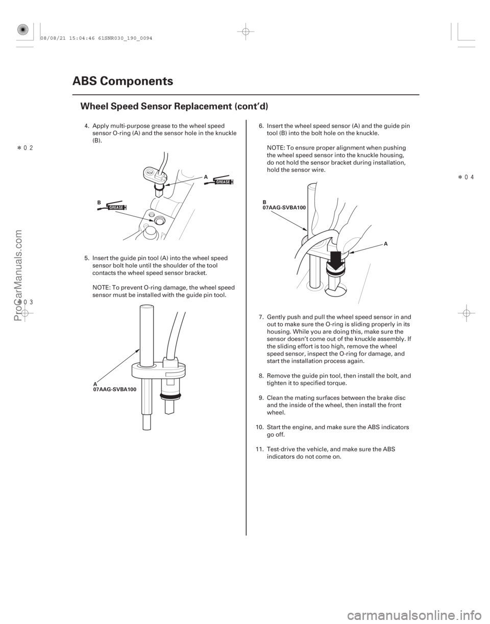
B
A
A
07AAG-SVBA100 B
07AAG-SVBA100
A
4. Apply multi-purpose grease to the wheel speedsensor O-ring (A) and the sensor hole in the knuckle
(B).
5. Insert the guide pin tool (A) into the wheel speed sensor bolt hole until the shoulder of the tool
contacts the wheel speed sensor bracket.
NOTE: To prevent O-ring damage, the wheel speed
sensor must be installed with the guide pin tool. 6. Insert the wheel speed sensor (A) and the guide pin
tool (B) into the bolt hole on the knuckle.
NOTE: To ensure proper alignment when pushing
the wheel speed sensor into the knuckle housing,
do not hold the sensor bracket during installation,
hold the sensor wire.
7. Gently push and pull the wheel speed sensor in and out to make sure the O-ring is sliding properly in its
housing. While you are doing this, make sure the
sensor doesn’t come out of the knuckle assembly. If
the sliding effort is too high, remove the wheel
speed sensor, inspect the O-ring for damage, and
start the installation process again.
8. Remove the guide pin tool, then install the bolt, and tighten it to specified torque.
9. Clean the mating surfaces between the brake disc and the inside of the wheel, then install the front
wheel.
10. Start the engine, and make sure the ABS indicators go off.
11. Test-drive the vehicle, and make sure the ABS indicators do not come on.
08/08/21 15:04:46 61SNR030_190_0094
ProCarManuals.com
DYNOMITE -2009-
Page 1667 of 2893

�����
����������
19-175
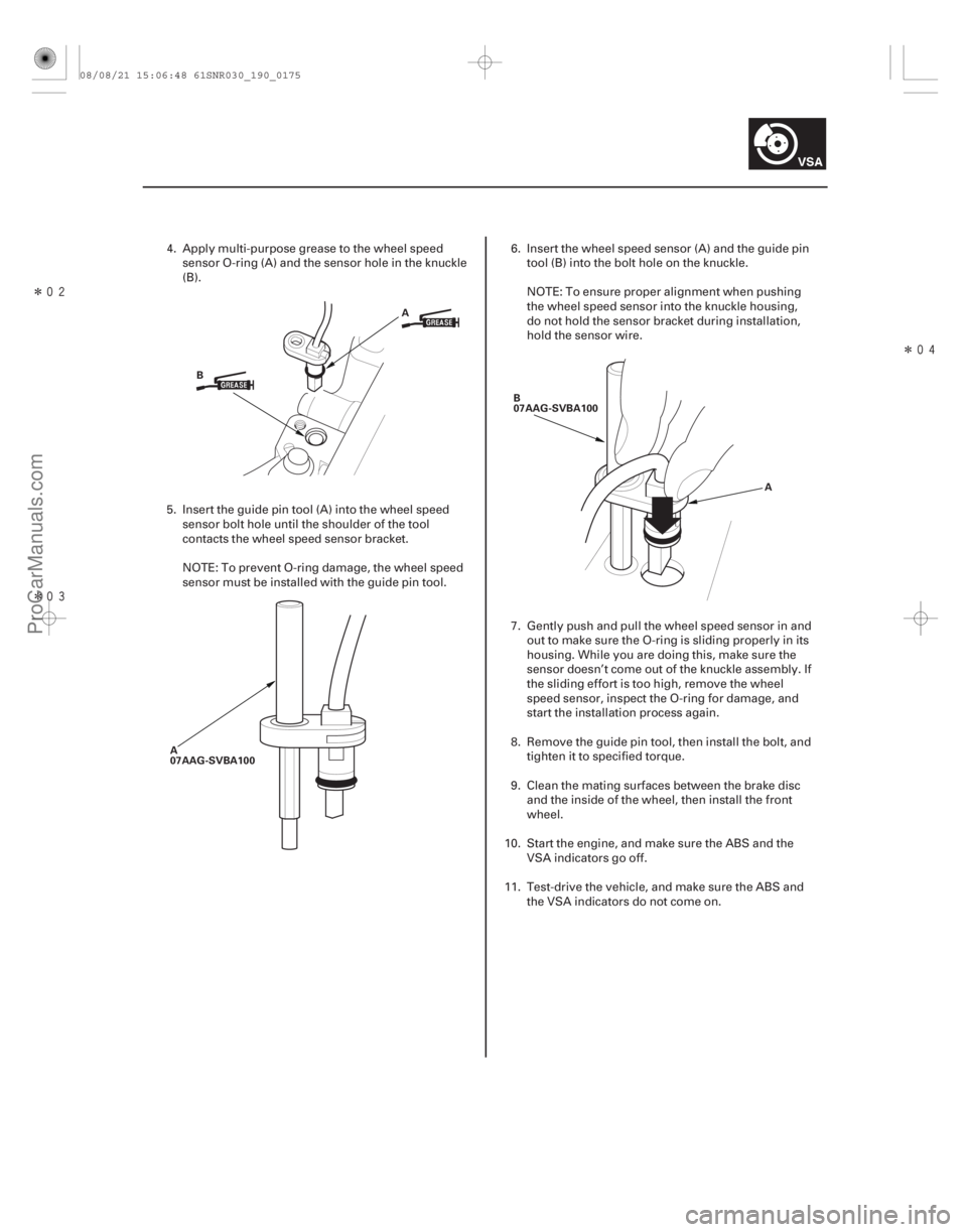
A
B
A
07AAG-SVBA100 B
07AAG-SVBA100
A
4. Apply multi-purpose grease to the wheel speedsensor O-ring (A) and the sensor hole in the knuckle
(B).
5. Insert the guide pin tool (A) into the wheel speed sensor bolt hole until the shoulder of the tool
contacts the wheel speed sensor bracket.
NOTE: To prevent O-ring damage, the wheel speed
sensor must be installed with the guide pin tool. 6. Insert the wheel speed sensor (A) and the guide pin
tool (B) into the bolt hole on the knuckle.
NOTE: To ensure proper alignment when pushing
the wheel speed sensor into the knuckle housing,
do not hold the sensor bracket during installation,
hold the sensor wire.
7. Gently push and pull the wheel speed sensor in and out to make sure the O-ring is sliding properly in its
housing. While you are doing this, make sure the
sensor doesn’t come out of the knuckle assembly. If
the sliding effort is too high, remove the wheel
speed sensor, inspect the O-ring for damage, and
start the installation process again.
8. Remove the guide pin tool, then install the bolt, and tighten it to specified torque.
9. Clean the mating surfaces between the brake disc and the inside of the wheel, then install the front
wheel.
10. Start the engine, and make sure the ABS and the VSA indicators go off.
11. Test-drive the vehicle, and make sure the ABS and the VSA indicators do not come on.
08/08/21 15:06:48 61SNR030_190_0175
ProCarManuals.com
DYNOMITE -2009-