Page 2094 of 2893
����
�(�#�'���������������������������������������)���
���
����
�(�#�'�������������������������������
�������)����
22-14622-146 Horns
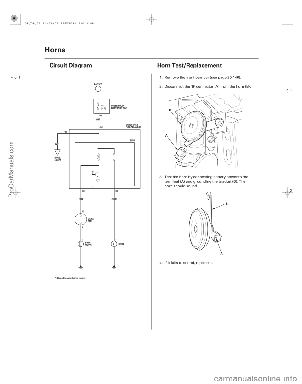
Circuit Diagram
Horn Test/Replacement
F31 G16
G7
Q3
HORN
* : Ground through steering column. * MICU
ORN LT GRN (15 A) No. 12
WHT
WHT BATTERY
UNDER-DASH
FUSE/RELAY BOX
BRAKE
LIGHTS
CABLE
REEL
HORN
SWITCH UNDER-HOOD
FUSE/RELAY BOX
D8
10 3
11A B
AB
1. Remove the front bumper (see page 20-146).
2. Disconnect the 1P connector (A) from the horn (B).
3. Test the horn by connecting battery power to the
terminal (A) and grounding the bracket (B). The
horn should sound.
4. If it fails to sound, replace it.
08/08/21 14:26:09 61SNR030_220_0148
ProCarManuals.com
DYNOMITE -2009-
Page 2116 of 2893
����
22-168 Exterior Lights
HID Bulb Replacement
A
C B A
A transient high tension (25,000 V) occurs at the
bulb sockets of the high intensity di")
���
����
�(�#�'�����!���������
�����
�
��������� �����)����
22-168 Exterior Lights
HID Bulb Replacement
A
C B A
A transient high tension (25,000 V) occurs at the
bulb sockets of the high intensity discharge (HID)
lamps when the combination light switch is turned
ON. It may cause serious electrical shock or
electrocution if you do not observe the cautions.
Never turn on the combination light switch before fitting the HID bulbs to their bulb sockets
and completing the reassembly of the headlight
assembly.
Do not service the headlight assembly in wet conditions, such as rain or snow, near a sprinkler
system, or when your hands are wet to prevent
electrocution.
Do not touch the surface of the HID bulbs with your bare hands and do not stain it with any oils
and fats.
Do not disassemble the inverter unit and the igniter fats.
Do not turn on the HID bulb by using a power source other than the battery mounted on your
vehicle.
1. Turn the combination light switch OFF.
2. Do the battery terminal disconnection procedure (see page 22-68).
3. Remove the battery. (left side bulb) 4. Turn the cover (A) 45 ° counterclockwise to remove
it from the headlight assembly.
5. Turn the socket (A) 45 ° counterclockwise to remove it from the bulb (B).
6. Pull the retaining spring (C) away from the bulb then remove the bulb.
7. Install the new bulb in the reverse order of removal. Make sure the notches in the bulb align with the
tabs in the headlight.
8. Install the parts in the reverse order of removal.
9. Do the battery terminal reconnection procedure (see page 22-68).
08/08/21 14:26:59 61SNR030_220_0170
ProCarManuals.com
DYNOMITE -2009-
Page 2117 of 2893
����
�(�#�'�����!���������
�����
���
�����
� �����)����
22-169
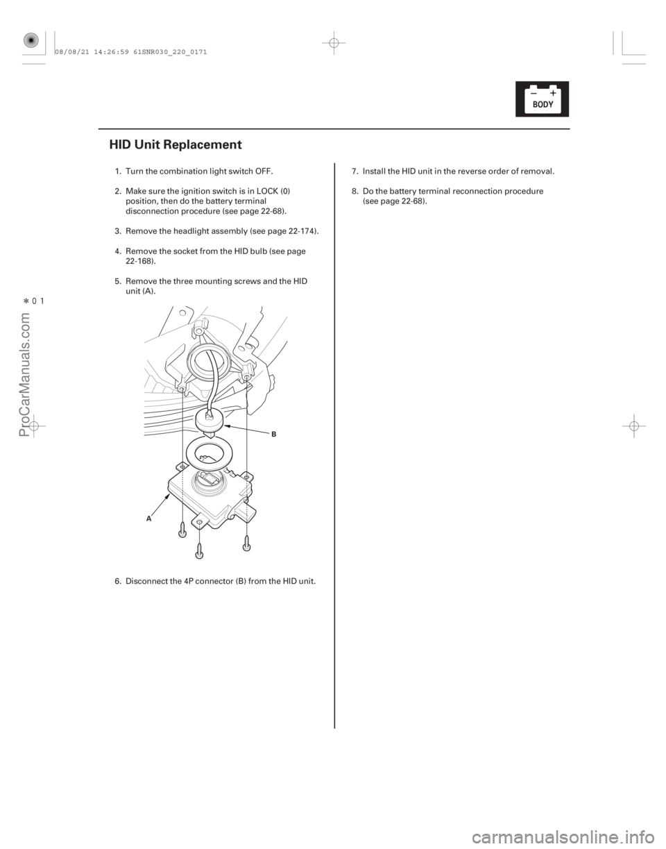
HID Unit Replacement
AB
1. Turn the combination light switch OFF.
2. Make sure the ignition switch is in LOCK (0)
position, then do the battery terminal
disconnection procedure (see page 22-68).
3. Remove the headlight assembly (see page 22-174).
4. Remove the socket from the HID bulb (see page 22-168).
5. Remove the three mounting screws and the HID unit (A).
6. Disconnect the 4P connector (B) from the HID unit. 7. Install the HID unit in the reverse order of removal.
8. Do the battery terminal reconnection procedure
(see page 22-68).
08/08/21 14:26:59 61SNR030_220_0171
ProCarManuals.com
DYNOMITE -2009-
Page 2148 of 2893
���� ���
�(�#����������������������������
���
� �����)���� Courtesy light: 3.4 W
22-19822-198
Interior Lights
Ambient Light Test/Replacement Cour")
����
�(�#�'�����������������������
���������������)���� ���
�(�#�'���������������������������
���
� �����)���� Courtesy light: 3.4 W
22-19822-198
Interior Lights
Ambient Light Test/Replacement Courtesy Light Replacement
A
B
C ’06-07 models
’08-09 models
A
B C
D
1. Remove the front individual map light.
With moonroof (see page 22-196)
Without moonroof (see page 22- 196)
2. Disconnect the 10P (or 12P ) connector (A) from the ambient light (B), then remove the ambient
light from the front individual map light housing (C).
1: ’06-07 models
2: ’08-09 models
3. Connect battery power to the terminal No. 5 and ground to the No. 3 terminal. The ambient light
should turn on. If the light does not turn on, replace
the ambient light.
4. Install the ambient light in the reverse order of removal. 1. Carefully pry off the lens (A) with a small
screwdriver.
2. Pry out the housing (B) from the door panel, then disconnect the 2P connector (C).
3. Separate the housing, then remove the bulb (D) from the socket.
4. Install the courtesy light in the reverse order of removal.
12
08/08/21 14:27:50 61SNR030_220_0200
ProCarManuals.com
DYNOMITE -2009-
Page 2170 of 2893
���
��������
����
�(�#�'���������������������������
�����������)���
Front passenger’s
Rear
22-220
Power Windows
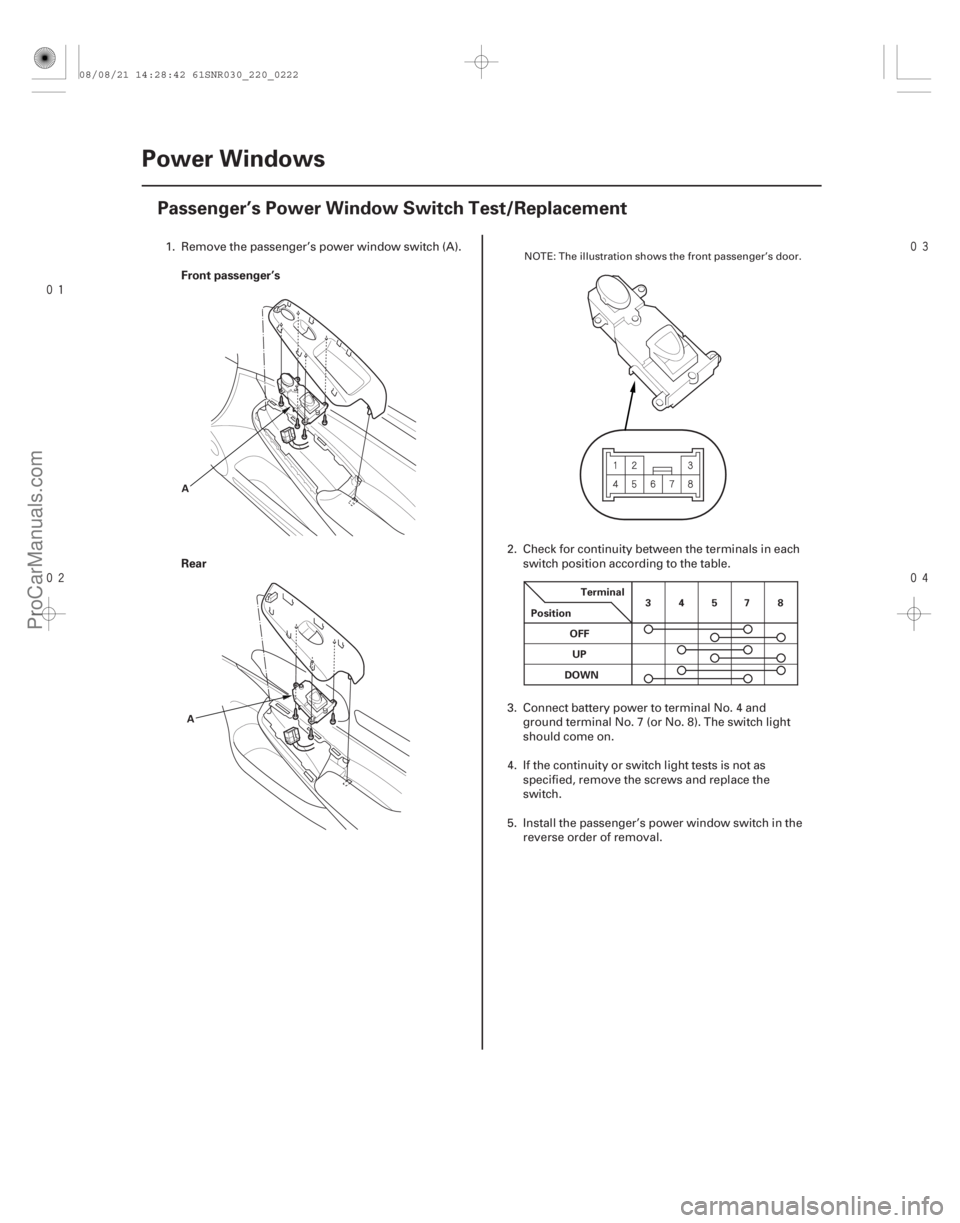
Passenger’s Power Window Switch Test/Replacement
A
A Terminal
Position 34578
OFF UP
DOWN
1. Remove the passenger’s power window switch (A).
2. Check for continuity between the terminals in eachswitch position according to the table.
3. Connect battery power to terminal No. 4 and ground terminal No. 7 (or No. 8). The switch light
should come on.
4. If the continuity or switch light tests is not as specified, remove the screws and replace the
switch.
5. Install the passenger’s power window switch in the reverse order of removal.NOTE: The illustration shows the front passenger’s door.
08/08/21 14:28:42 61SNR030_220_0222
ProCarManuals.com
DYNOMITE -2009-
Page 2219 of 2893
����
�µ
�µ
�µ
�µ �µ
�µ
�µ
�µ
DTC B1177:
YES
NO
YES
NO YES
NO
YES
NO
22-269
Battery Voltage Abnormal (’06
model)
NOTE: If you are troubleshooting")
�(�#�'��������� �������������.�
�
�����������)����
�µ
�µ
�µ
�µ �µ
�µ
�µ
�µ
DTC B1177:
YES
NO
YES
NO YES
NO
YES
NO
22-269
Battery Voltage Abnormal (’06
model)
NOTE: If you are troubleshooting multiple DTCs, be
sure to follow the instructions in B-CAN System
Diagnosis Test Mode A (see page 22-93).
1. Clear the DTCs with the HDS.
2. Turn the ignition switch to LOCK (0), and then back to ON (II).
3. Check for DTCs with the HDS.
Go to step 8.
Go to step 4.
4. Clear the DTCs with the HDS.
5. Turn the ignition switch to LOCK (0), and then back to ON (II).
6. Crank the engine.
7. Check for DTCs with the HDS.
Go to step 8.
Intermittent failure. The gauge control
module (tach) and power supply voltage (IG1) that
is supplied to the gauge control module (tach) are
OK at this time. The battery may have been
discharged, and recovered. 8. Check the battery (see page 22-67) and the
charging system.
Go to step 9.
The battery needs a recharge or replacement,
or the charging system needs to repaired.
9. Turn the ignition switch to ON (II).
10. With the gauge control module (tach) 36P connector still connected, measure the voltage
between gauge control module (tach) 36P
connector terminal No. 17 and body ground.
Replace the gauge control module (tach)
(see page 22-277).
Repair an open or high resistance in the BRN
wire between the ignition switch and the gauge
control module (tach).
I s DT C B117 7 i nd i cat ed ?
I s DT C B117 7 i nd i cat ed ? I s t he bat t er y cond i t i on nor mal and t he char gi ng
sy st em OK ?
I s t he v ol t age about 7 .5 V ?
08/08/21 14:35:58 61SNR030_220_0271
ProCarManuals.com
DYNOMITE -2009-
Page 2226 of 2893
���
Release Locked odometer mileage to the
original gauge control module.
22-276 Gauges
Rewriting the ODO Data and Transferring the Maintenance")
�µ�µ�µ
�(�#�'���������������
�����������������������)���
Release Locked odometer mileage to the
original gauge control module.
22-276 Gauges
Rewriting the ODO Data and Transferring the Maintenance Minder Data to a
New Gauge Control Module
NOTE:
Obtain a new gauge control module before starting the rewriting process.
Rewriting is not possible on a gauge control module that will not communicate with the HDS.
Make sure that the HDS shows the correct VIN for the car you are working on.
One you have started this procedure, you must complete it before removing the HDS from the DLC.
Connect a battery jump box (not a Battery charger) to insure that correct battery voltage will be maintained.
1. Before replacing the gauge control module, connect the HDS.
2. Select GAUGES from the BODY ELECTRICAL menu display.
3. Select ‘‘Gauge Control M odule Replacement (ODO
rewrite)’’ from the ADJUSTMENT menu, and follow
the instructions on the display to retrieve the ODO
data and the Maintenance Minder information.
4. Replace the gauge control module.
5. Follow the instructions on the display to write the new ODO data and Maintenance Minder data to a
new gauge control module. If the data transfer fails,
refer to the instructions below to release the locked
ODO data. If after you attempt to transfer mileage the odometer
has dashes ( ), garbled, or incorrect value
displayed, do the following start over. The original
gauge control module is going to be unlocked and
restored to its original state.
1. Confirm that you have the latest HDS version of software.
2. Make sure that the HDS shows the correct VIN for the car you are working on.
3. With the ignition switch to LOCK (0), reconnect the original gauge assembly.
4. Completely re-boot the HDS.
5. Clear any stored DTCs.
6. Navigation to Body. Electric/Gauges/Adjustment/Instrument Panel
Replacement.
7. Select ‘‘3. Releasing Locked ODO Data’’.
8. Follow the prompts and the Odometer mileage will be restored.
9. Start over and make sure the screen prompts are followed.
08/08/21 14:35:59 61SNR030_220_0278
ProCarManuals.com
DYNOMITE -2009-
Page 2246 of 2893
����
22-296 Accessory Power Sockets
Front Accessory Power Socket Test/Replacement
BLK
WHT
A B
A
A
NOTE: If both of the front and console acc")
���
����
����
�(�#�'�����������������
�
���
���������������)����
22-296 Accessory Power Sockets
Front Accessory Power Socket Test/Replacement
BLK
WHT
A B
A
A
NOTE: If both of the front and console accessory power
sockets do not work, check the No. 35 (7.5 A) fuse in the
under-dash fuse/relay box. 1. Remove the center panel. With audio:– ’06-08 models (see page 23-80)
– ’09 model (see page 23-256)
With navigation: – ’06-08 models (see page 23-155)
– ’09 model (see page 23-355)
2. Disconnect the 2P connector (A) from the front accessory power socket (B).
3. Inspect the connector terminals to be sure they are all making good contact.
If the terminals are bent, loose, or corroded, repair them as necessary and recheck the system.
IftheterminalslookOK,gotostep4.
4. Turn the ignition switch to ACC (I).
5. Measure the voltage between front accessory power socket 2P connector terminal No. 1 and body
ground. There should be battery voltage.
If there is battery voltage, go to step 6.
If there is no voltage, check for: – Blown No. 29 (15 A) fuse in the under-dash fuse/relay box.
– Faulty front accessory power socket relay.
– Poor ground (G 503).
– Anopeninthewire. 6. Check for continuity between front accessory
power socket 2P connector terminal No. 2 and body
ground. There should be continuity.
If there is continuity, replace the power socket; go to step 7.
If there is no continuity, check for: – Poor ground (G 502).
– Anopeninthewire.
7. Remove the socket (A).
8. Remove the housing (A) from the panel.
9. Install the front accessory power socket in the reverse order of removal.
Wire side of
female terminals
08/08/21 14:36:08 61SNR030_220_0298
ProCarManuals.com
DYNOMITE -2009-