����
�(�#�'���������������
�����������������������)����
Entering the self-diagnostic function with the HDS
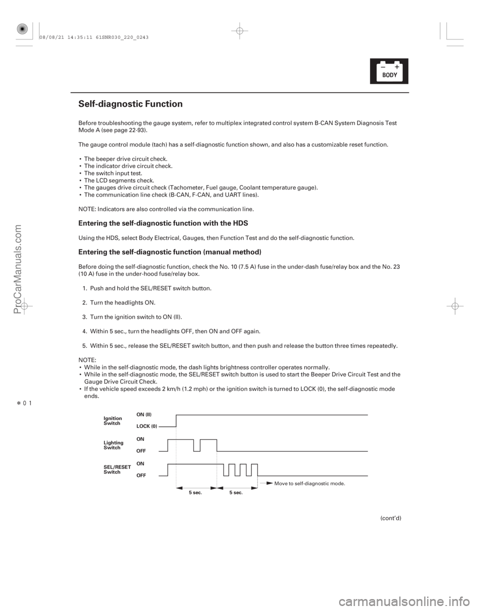
Entering the self-diagnostic function (manual method)
22-241
Self-diagnostic Function
ON (II)
OFF ON
OFF ON
Ignition
Switch
Lighting
Switch
SEL/RESET
Switch
5sec.
5sec.
LOCK (0)
Before troubleshooting the gauge system, refer to multiplex integrated control system B-CAN System Diagnosis Test
Mode A (see page 22-93).
The gauge control module (tach) has a self-diagnostic function shown, and also has a customizable reset function.
The beeper drive circuit check.
The indicator drive circuit check.
The switch input test.
The LCD segments check.
The gauges drive circuit check (Tachometer, Fuel gauge, Coolant temperature gauge).
The communication line check (B-CAN, F-CAN, and UART lines).
NOTE: Indicators are also controlled via the communication line.
Using the HDS, select Body Electrical, Gauges, then Function Test and do the self-diagnostic function.
Before doing the self-diagnostic function, check the No. 10 (7.5 A) fuse in the under-dash fuse/relay box and the No. 23
(10 A) fuse in the under-hood fuse/relay box. 1. Push and hold the SEL/RESET switch button.
2. Turn the headlights ON.
3. Turn the ignition switch to ON (II).
4. Within 5 sec., turn the headlights OFF, then ON and OFF again.
5. Within 5 sec., release the SEL/RESET switch button, and then push and release the button three times repeatedly.
NOTE: While in the self-diagnostic mode, the dash lights brightness controller operates normally.
While in the self-diagnostic mode, the SEL/RESET switch button is used to start the Beeper Drive Circuit Test and the Gauge Drive Circuit Check.
If the vehicle speed exceeds 2 km/h (1.2 mph) or the ignition switch is turned to LOCK (0), the self-diagnostic mode ends.
(cont’d)
Move to self-diagnostic mode.
08/08/21 14:35:11 61SNR030_220_0243
ProCarManuals.com
DYNOMITE -2009-
�¦�§ �¦ �§�¦ �§
�¦�§
�¦�§
�µ
�µ
Cavity Wire Test condition
Test: Desired result Possible cause if desired result
is not obtained
Cavity Wire Test condition Test: Desired result Possible cause if desired result
is not obtained
22-272Gauges
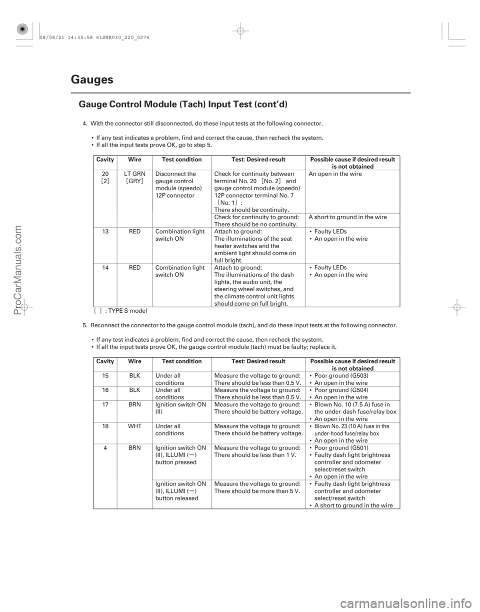
Gauge Control Module (Tach) Input Test (cont’d)
4. With the connector still disconnected, do these input tests at the following connector.
If any test indicates a problem, find and correct the cause, then recheck the system.
If all the input tests prove OK, go to step 5.
20
2 LT GRN
GRY Disconnect the
gauge control
module (speedo)
12P connector Check for continuity between
terminal No. 20 No. 2 and
gauge control module (speedo)
12P connector terminal No. 7
No. 1 :
There should be continuity. An open in the wire
Check for continuity to ground:
There should be no continuity. A short to ground in the wire
13 RED Combination light switch ON Attach to ground:
The illuminations of the seat
heater switches and the
ambient light should come on
full bright. Faulty LEDs
An open in the wire
14 RED Combination light switch ON Attach to ground:
The illuminations of the dash
lights, the audio unit, the
steering wheel switches, and
the climate control unit lights
should come on full bright. Faulty LEDs
An open in the wire
: TYPE S model
5. Reconnect the connector to the gauge control module (tach), and do these input tests at the following connector. If any test indicates a problem, find and correct the cause, then recheck the system.
If all the input tests prove OK, the gauge control module (tach) must be faulty; replace it.
15 BLK Under all
conditions Measure the voltage to ground:
There should be less than 0.5 V. Poor ground (G503)
An open in the wire
16 BLK Under all conditions Measure the voltage to ground:
There should be less than 0.5 V. Poor ground (G504)
An open in the wire
17 BRN Ignition switch ON (II) Measure the voltage to ground:
There should be battery voltage. Blown No. 10 (7.5 A) fuse in
the under-dash fuse/relay box
An open in the wire
18 WHT Under all conditions Measure the voltage to ground:
There should be battery voltage.
An open in the wire
4 BRN Ignition switch ON (II), ILLUMI ( )
button pressed Measure the voltage to ground:
There should be less than 1 V.
Poor ground (G501)
Faulty dash light brightness
controller and odometer
select/reset switch
An open in the wire
Ignition switch ON
(II), ILLUMI ( )
button released Measure the voltage to ground:
There should be more than 5 V.
Faulty dash light brightness
controller and odometer
select/reset switch
A short to ground in the wire
Blown No. 23 (10 A) fuse in the
under-hood fuse/relay box
08/08/21 14:35:58 61SNR030_220_0274
ProCarManuals.com
DYNOMITE -2009-