Page 2201 of 2893
�����
�µ
22-251
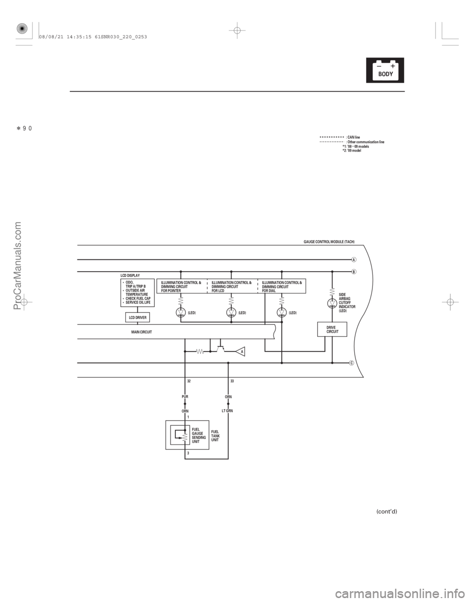
:CANline
MAIN CIRCUIT 33
ORN
ORN 32
LT GRN
3 1
PUR (LED)
(LED)
(LED)
C
LCD DISPLAY
B
A
GAUGE CONTROL MODULE (TACH)
ILLUMINATION CONTROL &
DIMMING CIRCUIT
FOR POINTER ILLUMINATION CONTROL &
DIMMING CIRCUIT
FOR LCDILLUMINATION CONTROL &
DIMMING CIRCUIT
FOR DIAL
FUEL
GAUGE
SENDING
UNIT FUEL
TANK
UNIT : Other communication line
DRIVE
CIRCUIT
A
ODO,
TRIP A/TRIP B
OUTSIDE AIR
TEMPERATURE
CHECK FUEL CAP
SERVICE OIL LIFE
LCD DRIVER SIDE
AIRBAG
CUTOFF
INDICATOR
(LED)*1: ’08 09 models
*2: ’09 model
(cont’d)
08/08/21 14:35:15 61SNR030_220_0253
ProCarManuals.com
DYNOMITE -2009-
Page 2208 of 2893
������(�#�'���������������
�����������������������)���
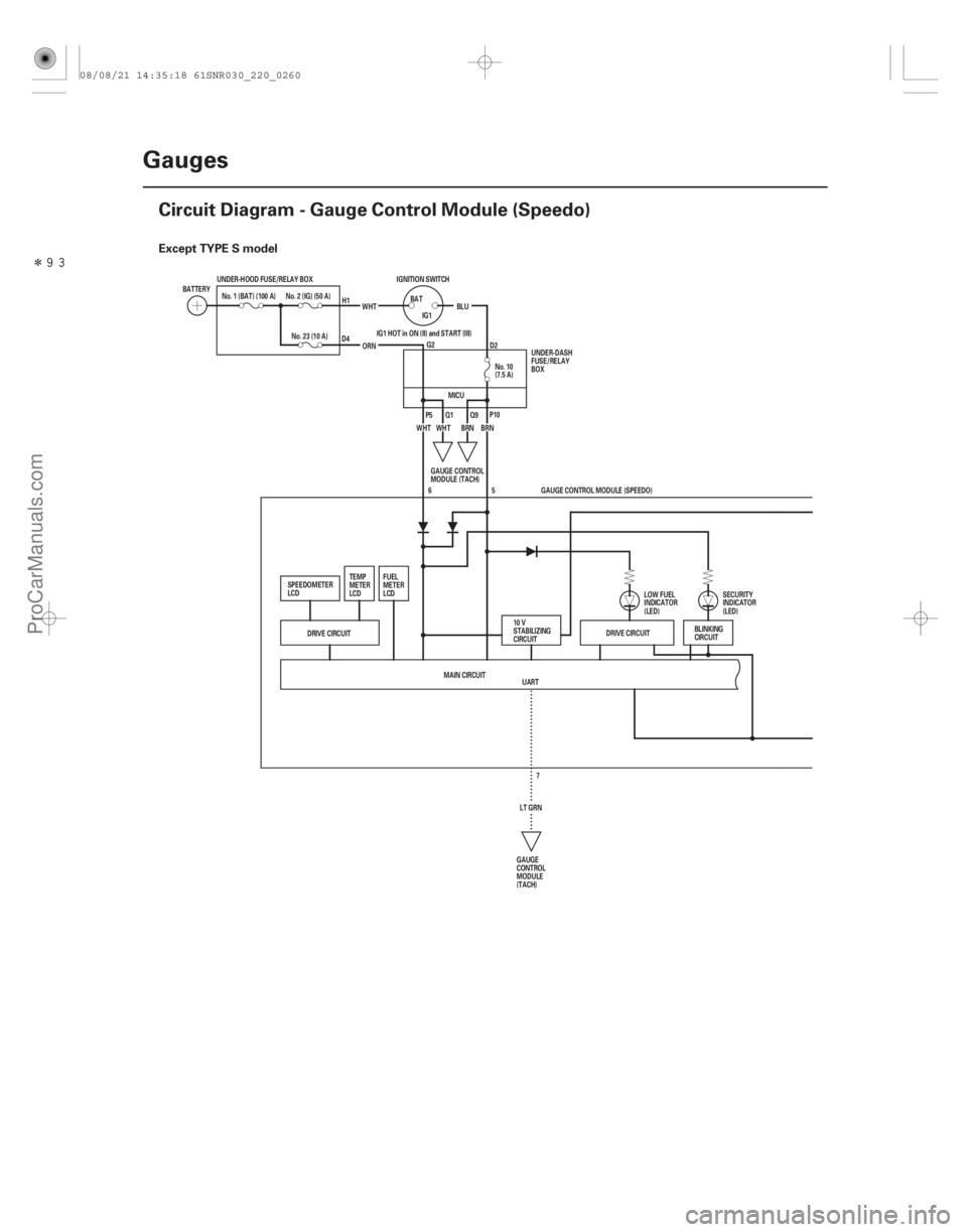
Except TYPE S model
22-258Gauges
Circuit Diagram - Gauge Control Module (Speedo)
UART
No. 10
(7.5 A)
No. 1 (BAT) (100 A)
IGNITION SWITCH
BATTERY
No. 23 (10 A)WHT
BLU
BAT
IG1
ORN
No. 2 (IG) (50 A)
BRN
WHT BRN
UNDER-HOOD FUSE/RELAY BOX
IG1 HOT in ON (II) and START (III)
WHT
DRIVE CIRCUIT DRIVE CIRCUIT
5
MAIN CIRCUIT LT GRN7GAUGE CONTROL MODULE (SPEEDO)
6
BLINKING
CIRCUIT
GAUGE
CONTROL
MODULE
(TACH)
10 V
STABILIZING
CIRCUIT
LOW FUEL
INDICATOR
(LED)
SECURITY
INDICATOR
(LED)
FUEL
METER
LCD
TEMP
METER
LCD
SPEEDOMETER
LCD GAUGE CONTROL
MODULE (TACH)UNDER-DASH
FUSE/RELAY
BOX
H1
D4 G2D2
P5 Q1 Q9P10
MICU
08/08/21 14:35:18 61SNR030_220_0260
ProCarManuals.com
DYNOMITE -2009-
Page 2209 of 2893
�����
22-259
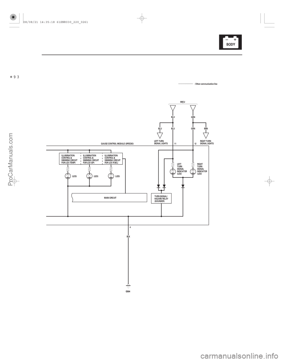
MICU
BLU GRN
BLU GRN
(LED)
(LED)
(LED)
G504G504 12
BRN
BLU
MAIN CIRCUIT BLK4
GAUGE CONTROL MODULE (SPEEDO) 11
ILLUMINATION
CONTROL &
DIMMING CIRCUIT
FOR LCD (TEMP) ILLUMINATION
CONTROL &
DIMMING CIRCUIT
FOR LCD (SP) ILLUMINATION
CONTROL &
DIMMING CIRCUIT
FOR LCD (FUEL)
LEFT
TURN
SIGNAL
INDICATOR
(LED)RIGHT
TURN
SIGNAL
INDICATOR
(LED)
TURN SIGNAL/
HAZARD RELAY
(SOUNDER) RIGHT TURN
SIGNAL LIGHTS
LEFT TURN
SIGNAL LIGHTS : Other communication line
08/08/21 14:35:18 61SNR030_220_0261
ProCarManuals.com
DYNOMITE -2009-
Page 2210 of 2893
������(�#�'���������������
�����������������������)���
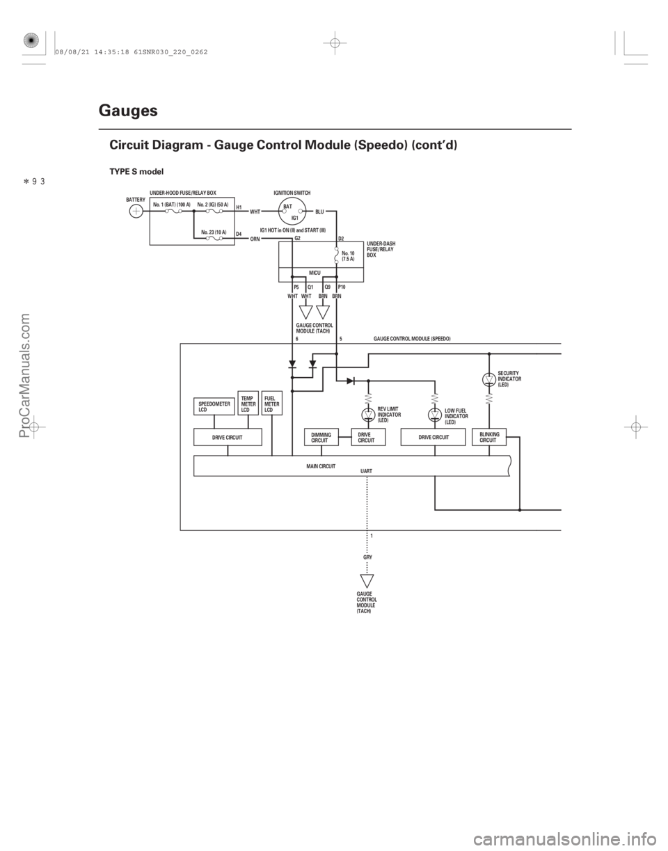
TYPE S model
22-260Gauges
Circuit Diagram - Gauge Control Module (Speedo) (cont’d)
UART
No. 10
(7.5 A)
No. 1 (BAT) (100 A)
IGNITION SWITCH
BATTERY
No. 23 (10 A)WHT
BLU
BAT
IG1
ORN
No. 2 (IG) (50 A)
BRN
WHT BRN
UNDER-HOOD FUSE/RELAY BOX
IG1 HOT in ON (II) and START (III)
WHT
DRIVE CIRCUIT DRIVE CIRCUIT
5
MAIN CIRCUIT GRY1GAUGE CONTROL MODULE (SPEEDO)
6
BLINKING
CIRCUIT
GAUGE
CONTROL
MODULE
(TACH) LOW FUEL
INDICATOR
(LED)
SECURITY
INDICATOR
(LED)
FUEL
METER
LCD
TEMP
METER
LCD
SPEEDOMETER
LCD GAUGE CONTROL
MODULE (TACH)UNDER-DASH
FUSE/RELAY
BOX
H1
D4 G2D2
P5 Q1 Q9P10
REV LIMIT
INDICATOR
(LED)
DIMMING
CIRCUIT DRIVE
CIRCUIT
MICU
08/08/21 14:35:18 61SNR030_220_0262
ProCarManuals.com
DYNOMITE -2009-
Page 2211 of 2893
�����
22-261
MICU
BLU GRN
BLU GRN
(LED)
(LED)
(LED)
G504G504 12
BRN
BLU
MAIN CIRCUIT BLK4
GAUGE CONTROL MODULE (SPEEDO) 11
ILLUMINATION
CONTROL &
DIMMING CIRCUIT
FOR LCD (TEMP) ILLUMINATION
CONTROL &
DIMMING CIRCUIT
FOR LCD (SP) ILLUMINATION
CONTROL &
DIMMING CIRCUIT
FOR LCD (FUEL)
LEFT
TURN
SIGNAL
INDICATOR
(LED)RIGHT
TURN
SIGNAL
INDICATOR
(LED)
TURN SIGNAL/
HAZARD RELAY
(SOUNDER) RIGHT TURN
SIGNAL LIGHTS
LEFT TURN
SIGNAL LIGHTS : Other communication line
08/08/21 14:35:19 61SNR030_220_0263
ProCarManuals.com
DYNOMITE -2009-
Page 2217 of 2893
����
�µ
�µ�µ �µ
�µ
�µ
DTC B1175:
YES
NO YES NO
YES
NO
22-267
FUEL TANK UNIT 4P CONNECTOR
GND (LT GRN)
JUMPER WIRE
FUEL UNIT
(ORN)
JUMPER")
���
����
�(�#�'��������� �������������.�
�
�����������)����
�µ
�µ�µ �µ
�µ
�µ
DTC B1175:
YES
NO YES NO
YES
NO
22-267
FUEL TANK UNIT 4P CONNECTOR
GND (LT GRN)
JUMPER WIRE
FUEL UNIT
(ORN)
JUMPER WIRE GAUGE CONTROL MODULE (TACH) 36P CONNECTOR
FUEL UNIT (PUR) GND (ORN)
Fuel Level Sensor (Fuel Gauge
Sending Unit) Circuit Open
NOTE: If you are troubleshooting multiple DTCs, be
sure to follow the instructions in B-CAN System
Diagnosis Test Mode A (see page 22-93).
1. Clear the DTCs with the HDS.
2. Turn the ignition switch to LOCK (0), and then back to ON (II).
3. Wait for 30 seconds.
4. Check for DTCs with the HDS.
Go to step 5.
Intermittent failure, the fuel level sensor
circuit is OK at this time. Check for loose or poor
connections.
5. Turn the ignition switch to LOCK (0).
6. Disconnect the fuel tank unit 5P connector and the gauge control module (tach) 36P connector.
7. Connect fuel tank unit 4P connector terminals No. 1 and No. 3 to body ground with jumper wires. 8. Check for continuity between gauge control
module (tach) 36P connector terminals No. 32 and
No. 33 and body ground individually.
Go to step 9.
Repair an open in the wire between the gauge
control module (tach) and the fuel tank unit.
9. Do the fuel gauge sending unit test (see page 11-340).
Replace the gauge control module (tach)
(see page 22-277).
Replace the fuel tank unit (see page 11-339).
Wire side of female terminals Wire side of female terminals
I s DT C B117 5 i nd i cat ed ?
Is there continuity?
I s t he f uel gauge send i ng uni t OK ?
08/08/21 14:35:20 61SNR030_220_0269
ProCarManuals.com
DYNOMITE -2009-
Page 2218 of 2893
����
�µ
�µ
�µ
�µ �µ
�µ
DTC B1176:
YES
NO
YES
NO YES
NO
22-268Gauges
DTC Troubleshooting (cont’d)
GAUGE CONTROL MODULE (TACH) 36P CONNECTOR")
����
�(�#�'��������� �������������.�
�
�����������)����
�µ
�µ
�µ
�µ �µ
�µ
DTC B1176:
YES
NO
YES
NO YES
NO
22-268Gauges
DTC Troubleshooting (cont’d)
GAUGE CONTROL MODULE (TACH) 36P CONNECTOR
FUEL UNIT (PUR)
Fuel Level Sensor (Fuel Gauge
Sending Unit) Circuit Short
NOTE: If you are troubleshooting multiple DTCs, be
sure to follow the instructions in B-CAN System
Diagnosis Test Mode A (see page 22-93).
1. Clear the DTCs with the HDS.
2. Turn the ignition switch to LOCK (0), and then back to ON (II).
3. Wait for 30 seconds.
4. Check for DTCs with the HDS.
Go to step 5.
Intermittent failure, the fuel level sensor
circuit is OK at this time. Check for loose or poor
connections.
5. Turn the ignition switch to LOCK (0).
6. Disconnect the fuel tank unit 4P connector.
7. Clear the DTCs with the HDS.
8. Turn the ignition switch to LOCK (0), and then back to ON (II).
9. Wait for 30 seconds.
10. Check for DTCs with the HDS.
Go to step 11.
Replace the fuel gauge sending unit (see page
11-340). 11. Disconnect the gauge control module (tach) 36P
connector.
12. Check for continuity between gauge control module (tach) 36P connector terminal No. 32 and
body ground.
Repair a short in the wire between the gauge
control module (tach) and the fuel tank unit.
Replace the gauge control module (tach)
(see page 22-277).
Wire side of female terminals
I s DT C B117 6 i nd i cat ed ?
I s DT C B117 6 i nd i cat ed ? Is there continuity?
08/08/21 14:35:20 61SNR030_220_0270
ProCarManuals.com
DYNOMITE -2009-
Page 2265 of 2893
����
22-315
System Description
Mechanical key
(Including transponder) Immobilizer key
MICU
(Imoes circuit) Mechanical key
Steering lock assembly Immob")
���
�(�#�'���������������������������������������)����
22-315
System Description
Mechanical key
(Including transponder) Immobilizer key
MICU
(Imoes circuit) Mechanical key
Steering lock assembly Immobilizer-keyless
control unit
ECM/PCMTransmitter
(Including
transponder)
The vehicle is equipped with a type VI immobilizer system that will disable the vehicle unless a programmed ignition
key is used.
This system consists of a transponder combined with a keyless transmitter, immob
ilizer-keyless control unit, the MICU
(has built-in imoes unit), immobilizer indicator, and the ECM/PCM.
When the immobilizer key (programmed by the HDS) is inserted into the ignition switch and turned to ON (II), the
immobilizer-keyless control unit sends power to the trans ponder in the ignition key. The transponder then sends a
coded signal back to the immobilizer-keyless control unit which then sends a coded signal to the ECM/PCM and the
MICU (imoes unit). The ECM/PCM and MICU (imoes unit) identify this code signal, then fuel power is supplied.
NOTE: The transmitter is automatically programmed to the vehicle when a transponder is programmed by the HDS.
If the wrong key has been used or the code was not received or recognized by the unit, the indicator will come on for
about 2 seconds, then it will blink until the ignition switch is turned to LOCK (0). When the ignition switch is turned to
LOCK (0), the indicator will blink ten times to signal that the unit has reset correctly, then the indicator will go off.
08/08/21 14:36:58 61SNR030_220_0317
ProCarManuals.com
DYNOMITE -2009-