Page 2117 of 2893
����
�(�#�'�����!���������
�����
���
�����
� �����)����
22-169
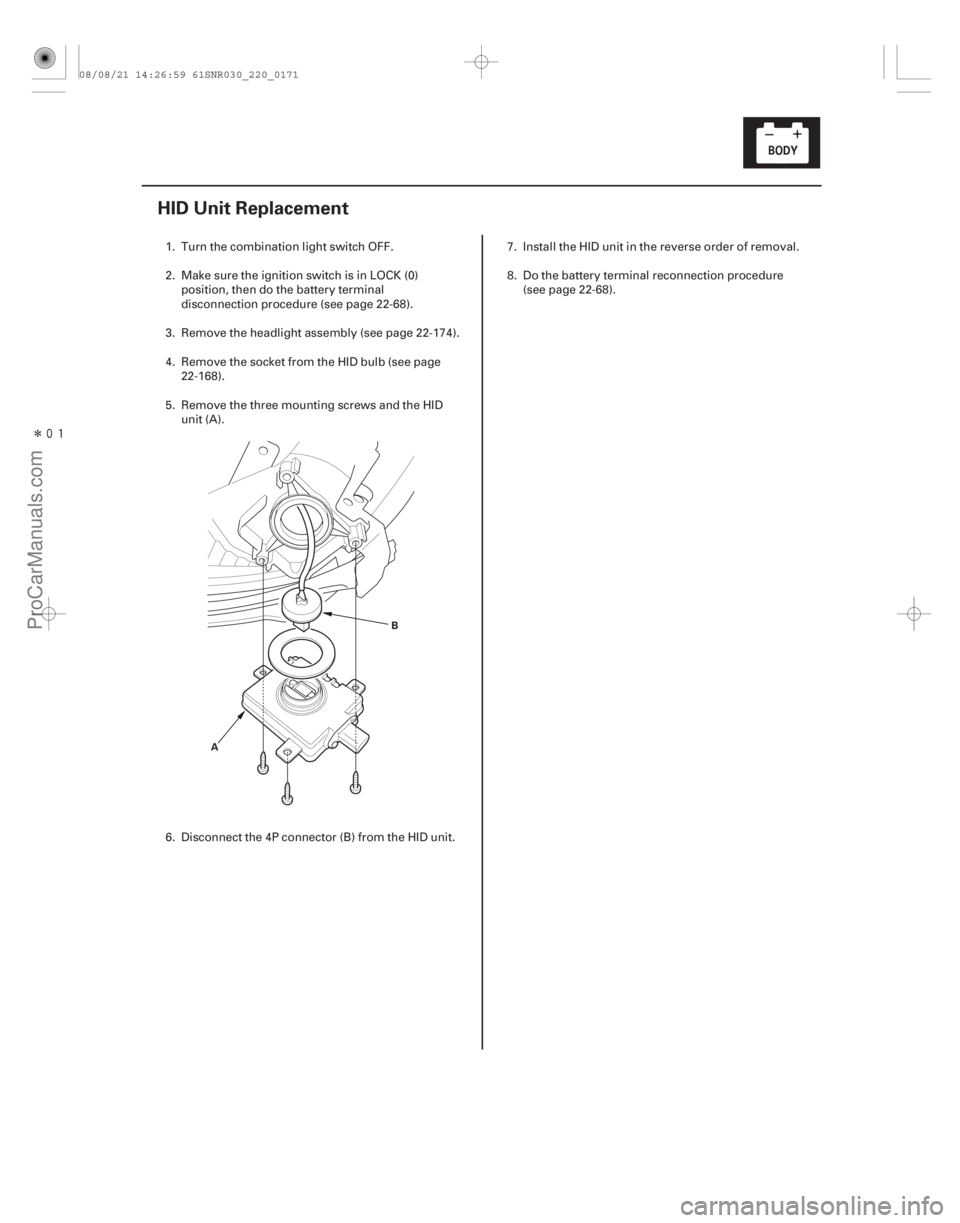
HID Unit Replacement
AB
1. Turn the combination light switch OFF.
2. Make sure the ignition switch is in LOCK (0)
position, then do the battery terminal
disconnection procedure (see page 22-68).
3. Remove the headlight assembly (see page 22-174).
4. Remove the socket from the HID bulb (see page 22-168).
5. Remove the three mounting screws and the HID unit (A).
6. Disconnect the 4P connector (B) from the HID unit. 7. Install the HID unit in the reverse order of removal.
8. Do the battery terminal reconnection procedure
(see page 22-68).
08/08/21 14:26:59 61SNR030_220_0171
ProCarManuals.com
DYNOMITE -2009-
Page 2118 of 2893
����
�µ
�µ �µ
�µ
Special Tools Required
YES
NO YES
NO
22-170Exterior Lights
HID Lamp System Troubleshooting
A
B
A transient high tension (25,000")
���
�(�#�'�����!���������
�����
�����������������)����
�µ
�µ �µ
�µ
Special Tools Required
YES
NO YES
NO
22-170Exterior Lights
HID Lamp System Troubleshooting
A
B
A transient high tension (25,000 V) occurs at the
bulb sockets or the high intensity discharge (HID)
lamps when the combination light switch is turned
ON, it may cause serious electrical shock or
electrocution if you do not observe the cautions.
Never turn on the combination light switch before fitting the HID bulbs to their bulb sockets
and completing the reassembly of the headlight
assembly.
Do not service the headlights assembly in wet conditions, such as rain or snow, near a sprinkler
system, or when your hands are wet to prevent
electrocution.
Do not touch the surface of the HID bulbs with your bare hands and do not stain it with any oils
and fats.
Do not disassemble the inverter unit and the igniter unit.
Do not turn on the HID bulb by using a power source other than the battery mounted on your
vehicle.
HID bulb test light 07AAJ-S3MA100
NOTE: Before troubleshooting the HID Lamp System,
do the multiplex integrated control system
troubleshooting using B-CAN System Diagnosis Test
Mode A (see page 22-93). 1. Check the No. 16 (15 A), No. 17 (15 A), and No. 21 (30 A) fuses in the under-dash fuse/relay box.
Go to step 2.
Replace the fuse(s), and recheck.
2. Turn the combination light switch OFF.
3. Do the battery terminal disconnection procedure (see page 22-68). 4. Remove the socket from the HID bulb (see page
22-168).
5. Check for corrosion (A) and traces of electrical arcing (B) at the socket mating part.
Go to step 7.
Replace the socket, and recheck.
Ar e f uses OK ? I s t he sock et cor r od ed or bur nt ?
08/08/21 14:27:00 61SNR030_220_0172
ProCarManuals.com
DYNOMITE -2009-
Page 2119 of 2893
 to the socket (B).
7. Do the battery terminal reconnection procedure(se")
��������
�µ
�µ �µ
�µ
YES
NO YES
NO
22-171
B
A
07AAJ-S3MA100 HID UNIT 2P CONNECTOR
BLK
6. Connect the HID bulb test light (A) to the socket (B).
7. Do the battery terminal reconnection procedure(see page 22-68).
8. Turn the combination light (headlight) switch ON.
Replace the original HID bulb (see page
22-168).
Go to step 10.
9. Turn the combination light (headlight) switch OFF.
10. Do the battery terminal disconnection procedure (see page 22-68).
11. Disconnect the HID bulb test light from the socket.
12. Do the battery terminal reconnection procedure (see page 22-68).
13. Disconnect the HID unit 2P connector.
14. Turn the combination light (headlight) switch ON. 15. Check for continuity between the HID unit 2P
connector terminal No. 1 and body ground.
Go to step 16.
Repair an open in the wire between the HID
unit and body ground. If the wire is OK, check for
poor ground at G201 or G301.
(cont’d)
Wire side of female terminals
Does t he bul b i n t he t est l i ght come on? Is there continuity?
08/08/21 14:27:00 61SNR030_220_0173
ProCarManuals.com
DYNOMITE -2009-
Page 2122 of 2893
����
22-17422-174 Exterior Lights
Headlight Adjustment (cont’d) Headlight Replacement
U: UP
D: DOWN
A A
D B
C
A
5. If necessary, open")
����
����
���
�(�#�'���������������
�����
���
�
���
� �����)����
22-17422-174 Exterior Lights
Headlight Adjustment (cont’d) Headlight Replacement
U: UP
D: DOWN
A A
D B
C
A
5. If necessary, open the hood and adjust the
headlights to local requirements by turning the
adjusters (A). A transient high tension (25,000 V) occurs at the bulb sockets or the high intensity discharge (HID)
lamps when the combination light switch is turned
ON, it may cause serious electrical shock or
electrocution if you do not observe the cautions.
Do not service the headlights assembly in wet
conditions, such as rain or snow, near a sprinkler
system, or when your hands are wet to prevent
electrocution.
1. Remove the front bumper (see page 20-146).
2. Remove the connectors (A) from the headlight assembly (B).
3. Remove the five bolts, then remove the headlight.
4. Remove the bolt (C) and the corner upper beam (D) from the headlight.
5. Install the headlight in the reverse order of removal.
6. After replacement, adjust the headlight to local requirements.
The illustration is shown from
back side of left headlight.
08/08/21 14:27:01 61SNR030_220_0176
ProCarManuals.com
DYNOMITE -2009-
Page 2123 of 2893
����
22-17422-174 Exterior Lights
Headlight Adjustment (cont’d) Headlight Replacement
U: UP
D: DOWN
A A
D B
C
A
5. If necessary, open")
����
����
���
�(�#�'���������������
�����
���
�
���
� �����)����
22-17422-174 Exterior Lights
Headlight Adjustment (cont’d) Headlight Replacement
U: UP
D: DOWN
A A
D B
C
A
5. If necessary, open the hood and adjust the
headlights to local requirements by turning the
adjusters (A). A transient high tension (25,000 V) occurs at the bulb sockets or the high intensity discharge (HID)
lamps when the combination light switch is turned
ON, it may cause serious electrical shock or
electrocution if you do not observe the cautions.
Do not service the headlights assembly in wet
conditions, such as rain or snow, near a sprinkler
system, or when your hands are wet to prevent
electrocution.
1. Remove the front bumper (see page 20-146).
2. Remove the connectors (A) from the headlight assembly (B).
3. Remove the five bolts, then remove the headlight.
4. Remove the bolt (C) and the corner upper beam (D) from the headlight.
5. Install the headlight in the reverse order of removal.
6. After replacement, adjust the headlight to local requirements.
The illustration is shown from
back side of left headlight.
08/08/21 14:27:01 61SNR030_220_0176
ProCarManuals.com
DYNOMITE -2009-
Page 2126 of 2893
����
���
����
�(�#�'���������������
�����
�
��������� �����)����
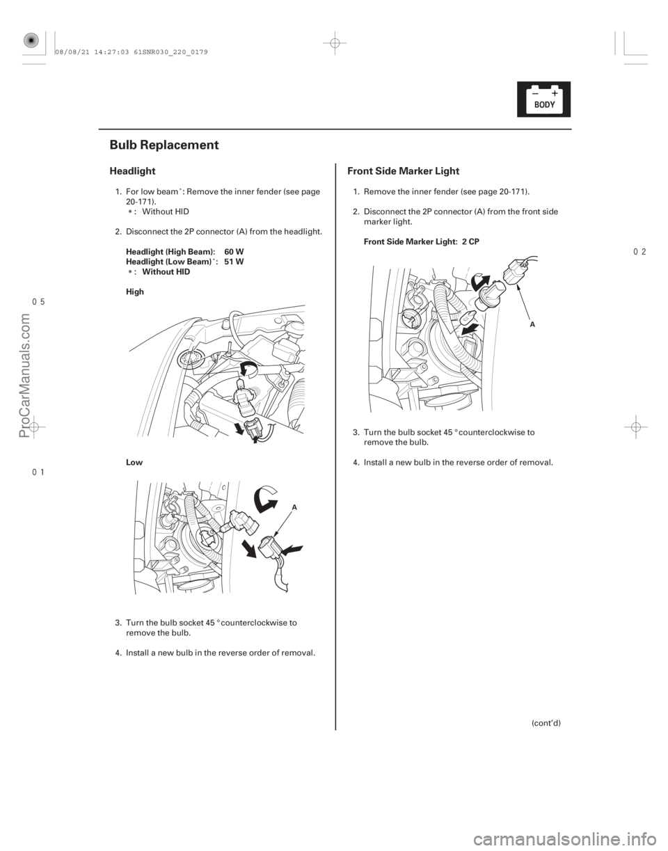
Headlight Front Side Marker Light
Headlight (High Beam): 60 W
Headlight (Low Beam) : 51 W
Without HID
High
Low Front Side Marker Light: 2 CP
22-177
Bulb Replacement
A
A
1. For low beam : Remove the inner fender (see page
20-171).: Without HID
2. Disconnect the 2P connector (A) from the headlight.
:
3. Turn the bulb socket 45 ° counterclockwise to remove the bulb.
4. Install a new bulb in the reverse order of removal. 1. Remove the inner fender (see page 20-171).
2. Disconnect the 2P connector (A) from the front side
marker light.
3. Turn the bulb socket 45 ° counterclockwise to remove the bulb.
4. Install a new bulb in the reverse order of removal.
(cont’d)
08/08/21 14:27:03 61SNR030_220_0179
ProCarManuals.com
DYNOMITE -2009-