Page 1589 of 2893

���
�(�#�'���������������
�����������������������)����
System IndicatorABS Indicator
Brake System Indicator
VSA Indicator
VSA Activation Indicator
19-97
General Troubleshooting Information
A
D B
C
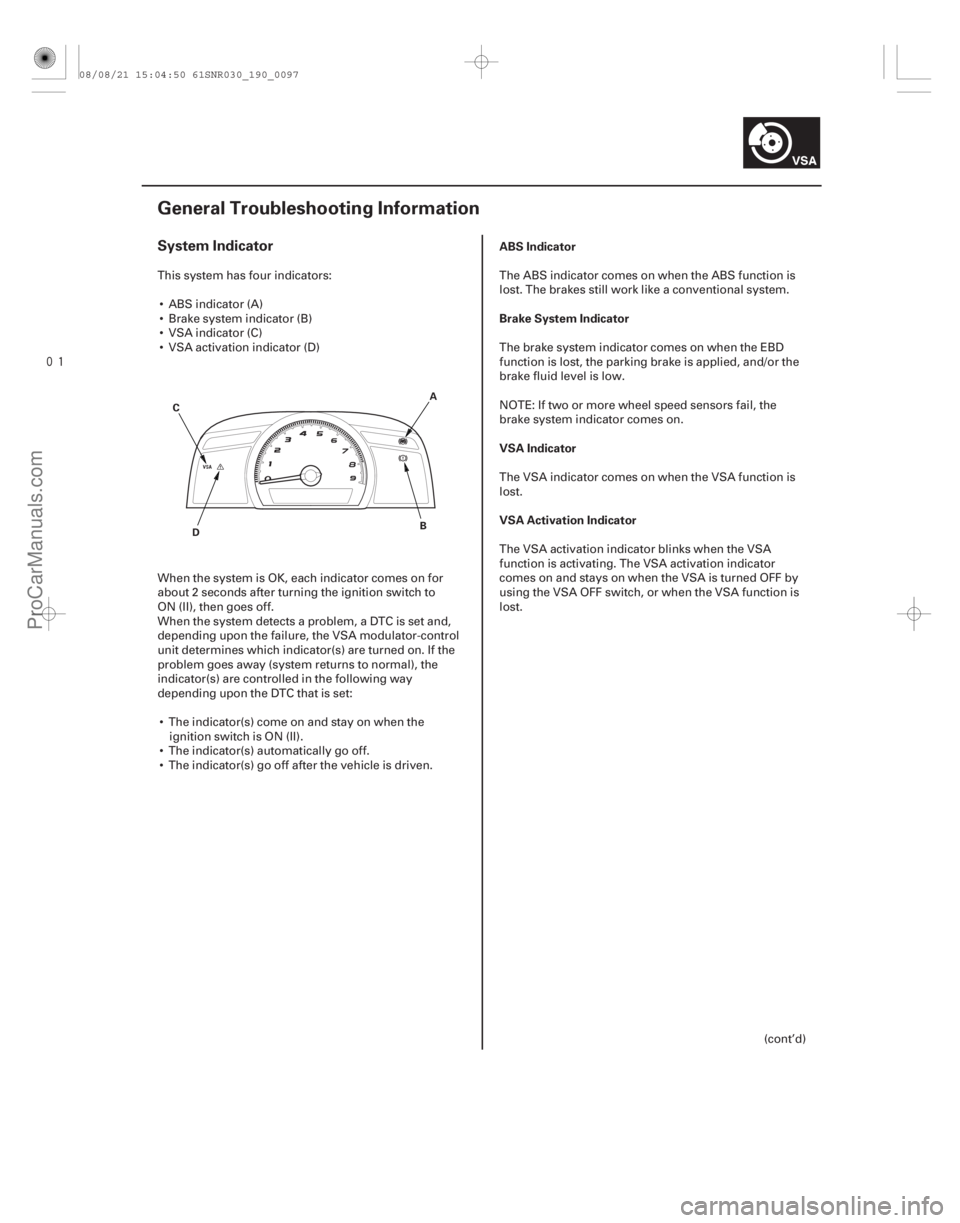
This system has four indicators:
ABS indicator (A)
Brake system indicator (B)
VSA indicator (C)
VSA activation indicator (D)
When the system is OK, each indicator comes on for
about 2 seconds after turning the ignition switch to
ON (II), then goes off.
When the system detects a problem, a DTC is set and,
depending upon the failure, the VSA modulator-control
unit determines which indicator(s) are turned on. If the
problem goes away (system returns to normal), the
indicator(s) are controlled in the following way
depending upon the DTC that is set: The indicator(s) come on and stay on when the ignition switch is ON (II).
The indicator(s) automatically go off.
The indicator(s) go off after the vehicle is driven. The ABS indicator comes on when the ABS function is
lost. The brakes still work like a conventional system.
The brake system indicator comes on when the EBD
function is lost, the parking brake is applied, and/or the
brake fluid level is low.
NOTE: If two or more wheel speed sensors fail, the
brake system indicator comes on.
The VSA indicator comes on when the VSA function is
lost.
The VSA activation indicator blinks when the VSA
function is activating. The VSA activation indicator
comes on and stays on when the VSA is turned OFF by
using the VSA OFF switch, or when the VSA function is
lost.
(cont’d)
08/08/21 15:04:50 61SNR030_190_0097
ProCarManuals.com
DYNOMITE -2009-
Page 1601 of 2893

����
����
ABS Features
Anti-lock control
Grip force of tire and road surface
Main Control
19-109
COEFFICIENT OF
FRICTIONTARGET SLIP RATE
ROTATIONAL
DIRECTION
RADIAL
DIRECTION
OF THE
ROTATIONAL
DIRECTION
SLIP RATE
LEFT-REAR
WHEEL SPEED
SENSOR RIGHT-REAR
WHEEL SPEED
SENSOR
LEFT-FRONT
WHEEL SPEED
SENSOR RIGHT-FRONT
WHEEL SPEED
SENSOR Select Low
Speed Wheel
Detect
Vehicle Speed
Drive
SolenoidRIGHT-REAR
SOLENOID
LEFT-REAR
SOLENOID
RIGHT-FRONT
SOLENOID
LEFT-FRONT
SOLENOID
CONTROL UNIT
ABS
Control
Reference
Slip Rate
Drive
Solenoid
ABS
Control
Drive
Solenoid
ABS
Control
Drive
Solenoid
ABS
Control
RIGHT-FRONT
LEFT-FRONT
Detect
Wheel Speed
Detect
Slip Rate
RIGHT-REAR
LEFT-REAR Detect
Slip Rate
Detect
Slip Rate
Detect
Slip Rate
Detect
Wheel Speed
Detect
Wheel Speed
Detect
Wheel Speed
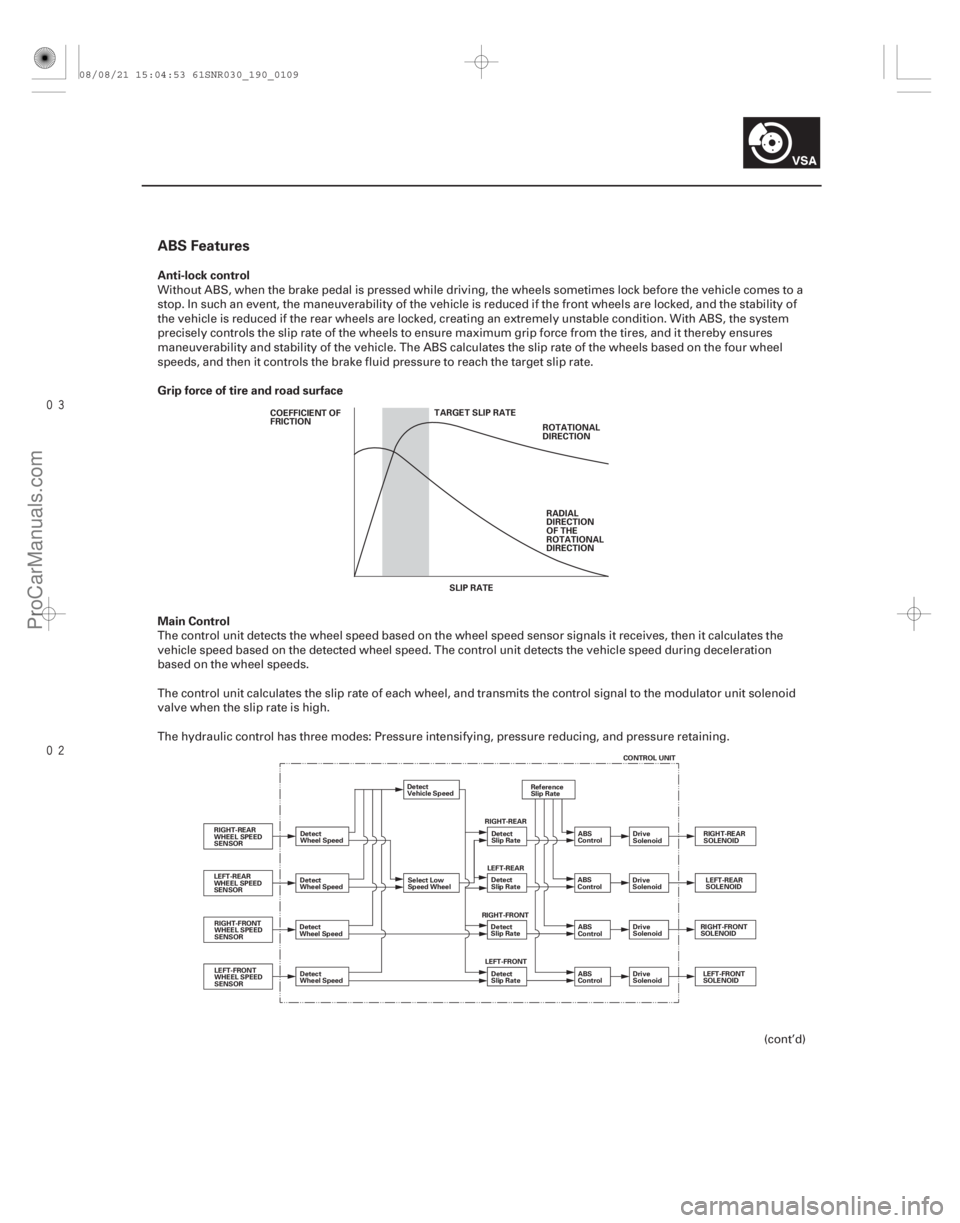
Without ABS, when the brake pedal is pressed while driving, the wheels sometimes lock before the vehicle comes to a
stop. In such an event, the maneuverability of the vehicle is reduced if the front wheels are locked, and the stability of
the vehicle is reduced if the rear wheels are locked, creating an extremely unstable condition. With ABS, the system
precisely controls the slip rate of the wheels to ensure maximum grip force from the tires, and it thereby ensures
maneuverability and stability of the vehicle. The ABS calculates the slip rate of the wheels based on the four wheel
speeds, and then it controls the brake fluid pressure to reach the target slip rate.
The control unit detects the wheel speed based on the wheel speed sensor signals it receives, then it calculates the
vehicle speed based on the detected wheel speed. The control unit detects the vehicle speed during deceleration
based on the wheel speeds.
The control unit calculates the slip rate of each wheel, and transmits the control signal to the modulator unit solenoid
valve when the slip rate is high.
The hydraulic control has three modes: Pressure intensifying, pressure reducing, and pressure retaining.
(cont’d)
08/08/21 15:04:53 61SNR030_190_0109
ProCarManuals.com
DYNOMITE -2009-
Page 1641 of 2893

�(�#�'��������� �����
�������'�����
���������)�����(�#�'��������� �����
�������'�������
�������)����
�µ
�µ
�µ
�µ �µ
�µ
�µ
�µ
DTC 66-15: DTC 68-21:
YES
NO
YES
NO YES
NO
YES
NO
19-14919-149
Pressure Sensor (Inside of VSA
Modulator-control Unit) Malfunction Brake Pedal Position Switch Stuck
OFF
1. Test-drive the vehicle.
NOTE: Drive the vehicle on the road, not on a lift.
2. Turn the ignition switch to LOCK (0).
3. Raise the vehicle, and support it with safety stands in the proper locations (see page 1-11).
4. Turn all four wheels by hand.
Repair the brake drag.
Go to step 5.
5. Turn the ignition switch to ON (II).
6. Check the BRAKE PRESS in the VSA DATA LIST with the HDS while moving the brake pedal.
Intermittent failure, the system is OK at this
time.
Replace the VSA modulator-control unit
(see page 19-171). 1. Start the engine.
2. Check the BRAKE PRESS in the VSA DATA LIST
with the HDS. Do not press the brake pedal.
Go to step 3.
Check for brake drag or a misadjusted brake
pedal position switch. If they are normal, replace
the VSA modulator-control unit (see page 19-171).
3. Check the BRAKE SWITCH in the VSA DATA LIST with the HDS while moving the brake pedal.
Intermittent failure, the system is OK at this
time. Check for loose terminals between the brake
pedal position switch 4P connector, ECM/PCM
connector A (44P), and the VSA modulator-control
unit 37P connector. Refer to intermittent failures
troubleshooting (see page 19-98).
Go to step 4.
4. Turn the ignition switch to LOCK (0).
5. Disconnect the brake pedal position switch 4P connector.
(cont’d)
Is there brake drag?Does t he i nd i cat ed v al ue change? I s t her e 10 M Pa or l ess?
Does i t i nd i cat e ON w hen t he ped al i s pr essed ,and OF F w hen t he ped al i s r el eased ?
08/08/21 15:05:58 61SNR030_190_0149
ProCarManuals.com
DYNOMITE -2009-