Page 1136 of 2893

A
C B
6x1.0mm
12 N·m
(1.2 kgf·m, 8.7 lbf·ft)
E
D
9. Remove the mounting bolts and A/T clutch
pr")
����
����
14-220Automatic Transmission
A/T Clutch Pressure Control Solenoid Valve A Test (cont’d)
A
C B
6x1.0mm
12 N·m
(1.2 kgf·m, 8.7 lbf·ft)
E
D
9. Remove the mounting bolts and A/T clutch
pressure control solenoid valve A.
10. Remove the ATF pipe (B), the ATF joint pipes (C), the O-rings (D), and the gasket (E).
11. Check the fluid passage of the solenoid valve for contamination. 12. Connect a jumper wire from the negative battery
terminal to A/T clutch pressure control solenoid
valve A connector terminal No. 2, and connect
another jumper wire from the positive battery
terminal to connector terminal No. 1. Make sure
A/T clutch pressure control solenoid valve A moves.
13. Disconnect one of the jumper wires, and check valve movement at the fluid passage in the valve
body mounting surface. If the valve binds or moves
sluggishly, or if the solenoid valve does not operate,
replace A/T clutch pressure control solenoid
valve A.
14. Clean the mounting surfaces and the fluid passages of the A/T clutch pressure control solenoid valve
body and the transmission housing.
15. Install a new gasket on the transmission housing, and install the ATF pipe and the ATF joint pipes.
NOTE: Be sure to install a new gasket with the blue
side toward the transmission housing.
16. Install new O-rings over the ATF joint pipes.
17. Install A/T clutch pressure control solenoid valve A.
18. Check the connectors for rust, dirt, or oil, clean or repair if necessary, then connect the connectors
securely.
19. Install the air cleaner assembly (see page 11-345) and the intake air duct (see page 11-348).
Replace.
Replace.
08/08/21 14:46:46 61SNR030_140_0222
ProCarManuals.com
DYNOMITE -2009-
Page 1137 of 2893
����
14-221
A/T Clutch Pressure Control Solenoid Valve A Replacement
A
C B
6x1.0mm
12 N·m
(1.2 kgf·m, 8.7 lbf·ft)
E
D
1. Remove the intake air d")
����
�(�#�'�������
���
�����
�����
��������� �����)����
14-221
A/T Clutch Pressure Control Solenoid Valve A Replacement
A
C B
6x1.0mm
12 N·m
(1.2 kgf·m, 8.7 lbf·ft)
E
D
1. Remove the intake air duct (see page 11-348) and
the air cleaner assembly (see page 11-345).
2. Disconnect the A/T clutch pressure control solenoid valve A connector.
3. Remove the mounting bolts and A/T clutch pressure control solenoid valve A.
4. Remove the ATF pipe (B), the ATF joint pipes (C), the O-rings (D), and the gasket (E). 5. Clean the mounting surface and the fluid passage
of the transmission housing.
6. Install a new gasket on the transmission housing, and install the ATF pipe and the ATF joint pipes.
NOTE: Be sure to install a new gasket with the blue
side toward the transmission housing.
7. Install new O-rings over the ATF joint pipes.
8. Install a new A/T clutch pressure control solenoid valve A.
9. Check the connector for rust, dirt, or oil, and clean or repair if necessary, then connect it securely.
10. Install the air cleaner assembly (see page 11-345) and the intake air duct (see page 11-348).
Replace.
Replace.
08/08/21 14:46:47 61SNR030_140_0223
ProCarManuals.com
DYNOMITE -2009-
Page 1139 of 2893
 F
E
B
9. Remove the mounting bolts, the harness clampbrackets (A), and A/T clutch pressure control
solenoid valves B and C.
10. Rem")
���������
14-223
AD
BC
A
6x1.0mm
12 N·m (1.2 kgf·m, 8.7 lbf·ft) F
E
B
9. Remove the mounting bolts, the harness clampbrackets (A), and A/T clutch pressure control
solenoid valves B and C.
10. Remove the ATF joint pipes (D), the O-rings (E), and the gasket (F).
11. Check the fluid passage of the solenoid valves for contamination. 12. Connect a jumper wire from the negative battery
terminal to A/T clutch pressure control solenoid
valve B connector terminal No. 2, and connect
another jumper wire from the positive battery
terminal to connector terminal No. 1. Make sure
A/T clutch pressure control solenoid valve B moves.
13. Disconnect one of the jumper wires, and check valve movement at the fluid passage in the valve
body mounting surface. If the valve binds or moves
sluggishly, or if the solenoid valve does not operate,
replace A/T clutch pressure control solenoid valves
BandC.
14. Clean the mounting surfaces and the fluid passages of the A/T clutch pressure control solenoid valve
body and the transmission housing.
15. Install a new gasket on the transmission housing.
NOTE: Be sure to install a new gasket with the blue
side toward the transmission housing.
16. Install the ATF joint pipes, and install new O-rings over the ATF joint pipes.
17. Install A/T clutch pressure control solenoid valves B and C.
18. Check the connectors for rust, dirt, or oil, clean or repair if necessary, then connect the connectors
securely.
19. Install the air cleaner assembly (see page 11-345) and the intake air duct (see page 11-348).
Replace.
Replace.
08/08/21 14:46:48 61SNR030_140_0225
ProCarManuals.com
DYNOMITE -2009-
Page 1141 of 2893
 F
E
C
9. Remove the mounting bolts, the harness clampbrackets (A), and A/T clutch pressure control
solenoid valves B and C.
10. Rem")
���������
14-225
AD
BC
A
6x1.0mm
12 N·m (1.2 kgf·m, 8.7 lbf·ft) F
E
C
9. Remove the mounting bolts, the harness clampbrackets (A), and A/T clutch pressure control
solenoid valves B and C.
10. Remove the ATF joint pipes (D), the O-rings (E), and the gasket (F).
11. Check the fluid passage of the solenoid valves for contamination. 12. Connect a jumper wire from the negative battery
terminal to A/T clutch pressure control solenoid
valve C connector terminal No. 2, and connect
another jumper wire from the positive battery
terminal to connector terminal No. 1. Make sure
A/T clutch pressure control solenoid valve C moves.
13. Disconnect one of the jumper wires, and check valve movement at the fluid passage in the valve
body mounting surface. If the valve binds or moves
sluggishly, or if the solenoid valve does not operate,
replace A/T clutch pressure control solenoid valves
BandC.
14. Clean the mounting surfaces and the fluid passages of the A/T clutch pressure control solenoid valve
body and the transmission housing.
15. Install a new gasket on the transmission housing.
NOTE: Be sure to install a new gasket with the blue
side toward the transmission housing.
16. Install the ATF joint pipes, and install new O-rings over the ATF joint pipes.
17. Install A/T clutch pressure control solenoid valves B and C.
18. Check the connectors for rust, dirt, or oil, clean or repair if necessary, then connect the connectors
securely.
19. Install the air cleaner assembly (see page 11-345) and the intake air duct (see page 11-348).
Replace.
Replace.
08/08/21 14:46:49 61SNR030_140_0227
ProCarManuals.com
DYNOMITE -2009-
Page 1142 of 2893
�
��
14-226Automatic Transmission
A/T Clutch Pressure Control Solenoid Valve B and C Replacement
A
D
BC
A
6x1.0mm
12 N·m (1.2 kgf·m, 8.7 lbf·ft)")
������(�#�'�������
���
�����
�����
��������� �����)�
��
14-226Automatic Transmission
A/T Clutch Pressure Control Solenoid Valve B and C Replacement
A
D
BC
A
6x1.0mm
12 N·m (1.2 kgf·m, 8.7 lbf·ft) F
E
1. Remove the intake air duct (see page 11-348) and the air cleaner assembly (see page 11-345).
2. Disconnect the A/T clutch pressure control solenoid valves B and C connectors.
3. Remove the mounting bolts, the harness clamp brackets (A), and A/T clutch pressure control
solenoid valves B and C.
4. Remove the ATF joint pipes (D), the O-rings (E), and the gasket (F). 5. Clean the mounting surface and the fluid passage
of the transmission housing.
6. Install a new gasket on the transmission housing, and install the ATF joint pipes.
NOTE: Be sure to install a new gasket with the blue
side toward the transmission housing.
7. Install new O-rings over the ATF joint pipes.
8. Install new A/T clutch pressure control solenoid valves B and C, and harness clamp brackets.
9. Check the connectors for rust, dirt, or oil, clean or repair if necessary, then connect it securely.
10. Install the air cleaner assembly (see page 11-345) and the intake air duct (see page 11-348).
Replace.
Replace.
08/08/21 14:46:49 61SNR030_140_0228
ProCarManuals.com
DYNOMITE -2009-
Page 1278 of 2893
 6x1.0mm
12 N·m
(1.2 kgf·m, 8.7 lbf·ft)
A D
B C
E D
B
C A
6x1.0mm
12 N·m (1.2 kgf·m, 8.7 lbf·ft)
25. Install the trans")
�
��
�
���
��
�����
14-353
A
B C
6x1.0mm
12 N·m (1.2 kgf·m, 8.7 lbf·ft) 6x1.0mm
12 N·m
(1.2 kgf·m, 8.7 lbf·ft)
A D
B C
E D
B
C A
6x1.0mm
12 N·m (1.2 kgf·m, 8.7 lbf·ft)
25. Install the transmission range switch (A) gently on the selector control shaft (B) while holding it in the
N position using the 2.0 mm (0.08 in.) blade (C).
26. Tighten the bolts on the transmission range switch while you continue to hold it in the N position. Do
not move the transmission range switch when
tightening the bolts. Remove the feeler gauge. 27. Connect the transmission range switch connector
(A) securely, then install the harness clamps (B) on
the clamp bracket (C).
28. Install the transmission range switch cover (D).
29. Install a new gasket (B) on the transmission housing, and install the ATF pipe (C) and the ATF
joint pipes (D).
NOTE: Be sure to install a new gasket with the blue
side toward the transmission housing.
30. Install new O-rings (E) over the ATF joint pipes, and install A/T clutch pressure control solenoid valve A.
(cont’d)
Replace.
08/08/21 14:52:38 61SNR030_140_0355
ProCarManuals.com
DYNOMITE -2009-
Page 1279 of 2893
�����
��
�
��
14-354Transmission End Cover
End Cover Installation (cont’d)
A
D
E
B
C
F6x1.0mm
12 N·m
(1.2 kgf·m,
8.7 lbf·ft)
F
B
28N·m(2.9kgf·m,21lbf·ft)
E
28 N·m (2.9 kgf·m, 21 lbf·ft) C
C A
D F
F
A
B
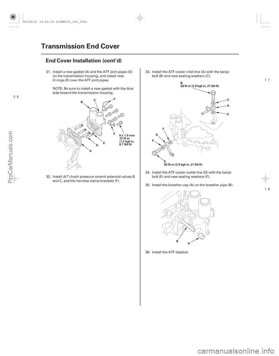
31. Install a new gasket (A) and the ATF joint pipes (D)
on the transmission housing, and install new
O-rings (E) over the ATF joint pipes.
NOTE: Be sure to install a new gasket with the blue
side toward the transmission housing.
32. Install A/T clutch pressure control solenoid valves B and C, and the harness clamp brackets (F). 33. Install the ATF cooler inlet line (A) with the banjo
bolt (B) and new sealing washers (C).
34. Install the ATF cooler outlet line (D) with the banjo bolt (E) and new sealing washers (F).
35. Install the breather cap (A) on the breather pipe (B).
36. Install the ATF dipstick.
08/08/21 14:52:39 61SNR030_140_0356
ProCarManuals.com
DYNOMITE -2009-
Page 1687 of 2893
����
20-1620-16 Doors
Front Door Glass Outer
Weatherstrip Replacement (cont’d)
Front Door Weatherstrip
Replacement
A
B
A
Fastener Loc")
����
����
�������
�(�#�'�����������
���
���������������
� �����)����
20-1620-16 Doors
Front Door Glass Outer
Weatherstrip Replacement (cont’d)
Front Door Weatherstrip
Replacement
A
B
A
Fastener Locations :Bolt,1
A :Clip,14
B
:Clip,2
C
:Clip,1
D
B
C
AC
F
E D
8x1.25mm
29 N·m
(3.0 kgf·m, 22 lbf·ft) E
(White)
(Black) (Left: Pink
Right: Blue)
4. Slide the front door glass outer weatherstrip (A)
forward.
5. Twist the front door glass outer weatherstrip (A) to pull the rear hook (B) out from the inside of the
door, then remove the weatherstrip.
6. Push the clip portions of new front door glass outer weatherstrip into place securely. NOTE:
Put on gloves to protect your hands.
Take care not to scratch the door.
Remove the clips with a clip remover.
1. At the A-pillar, remove the door checker mounting
bolt (A).
2. Detach the clips (B, C, D), then remove the door weatherstrip (E).
3. Install the weatherstrip in the reverse order of removal, and note these items:
If the clips are damaged or stress-whitened, replace them with new ones.
Make sure the weatherstrip is installed in the holder (F) securely.
Apply medium strength liquid thread lock to door checker mounting bolt before installation.
When reinstalling the door panel, make sure the
plastic cover is installed properly and sealed
around its outside perimeter to seal out water.
Check for water leaks (see step 9 on page 20-29).
08/08/21 14:59:03 61SNR030_200_0018
ProCarManuals.com
DYNOMITE -2009-