Page 2092 of 2893
����
22-144Keyless/Power Door Locks/Security System
Transmitter Test/Replacement (cont’d)
A
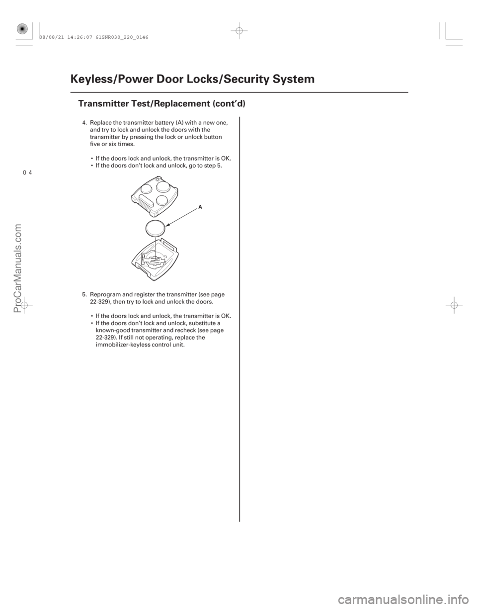
4. Replace the transmitter battery (A) with a new one,
and try to lock and unlock the doors with the
transmitter by pressing the lock or unlock button
five or six times.
If the doors lock and unlock, the transmitter is OK.
If the doors don’t lock and unlock, go to step 5.
5. Reprogram and register the transmitter (see page 22-329), then try to lock and unlock the doors.
If the doors lock and unlock, the transmitter is OK.
If the doors don’t lock and unlock, substitute a known-good transmitter and recheck (see page
22-329). If still not operating, replace the
immobilizer-keyless control unit.
08/08/21 14:26:07 61SNR030_220_0146
ProCarManuals.com
DYNOMITE -2009-
Page 2152 of 2893
����
�(�#�'���������������������������������������)����
22-202Entry Lights Control System
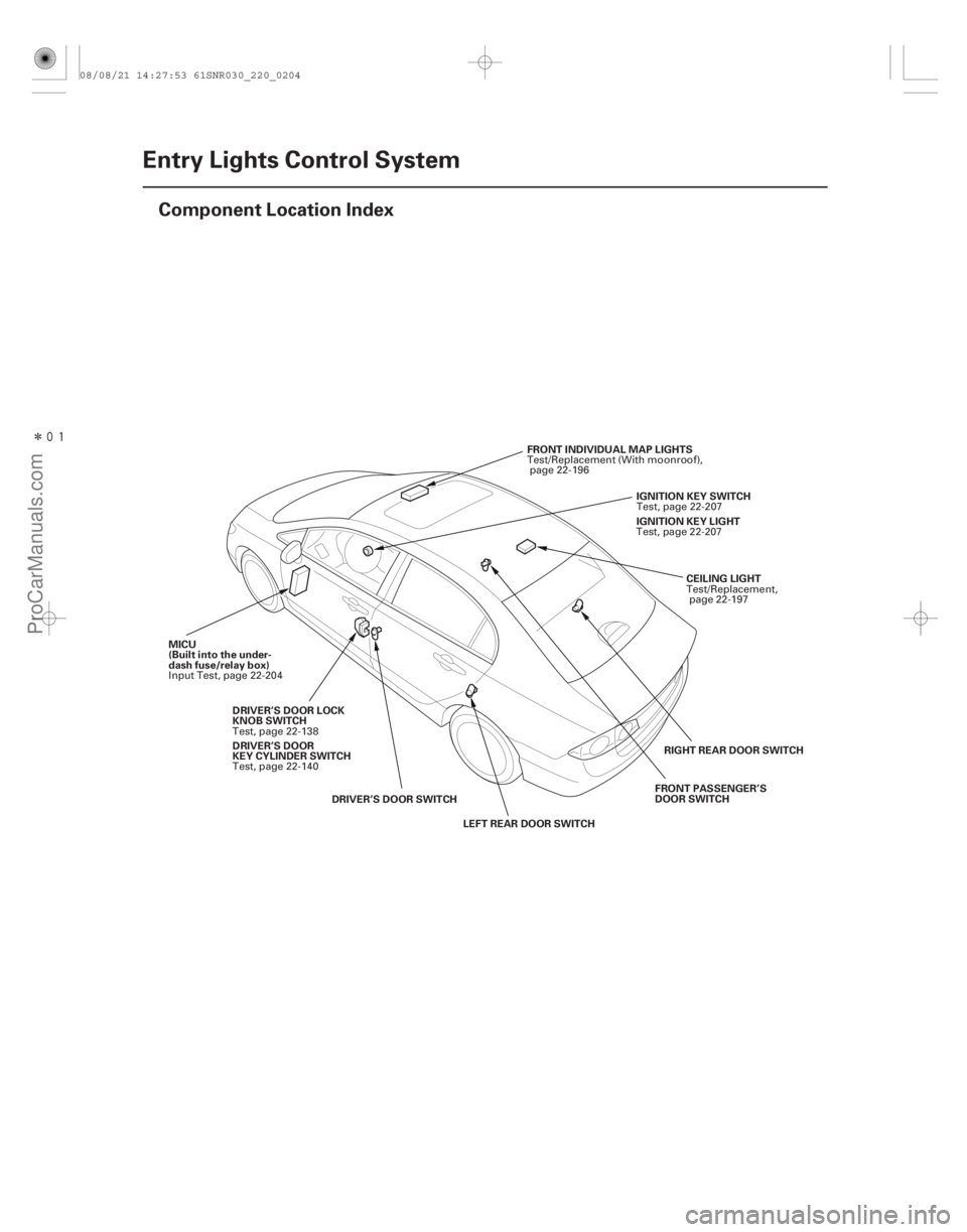
Component Location Index
CEILING LIGHT
FRONT INDIVIDUAL MAP LIGHTS
MICU
(Built into the under-
dash fuse/relay box) IGNITION KEY SWITCH
DRIVER’S DOOR SWITCH LEFT REAR DOOR SWITCH RIGHT REAR DOOR SWITCH
FRONT PASSENGER’S
DOOR SWITCH
DRIVER’S DOOR LOCK
KNOB SWITCH IGNITION KEY LIGHT
DRIVER’S DOOR
KEY CYLINDER SWITCH Test/Replacement,
page 22-197
Test/Replacement (With moonroof),
page 22-196
Input Test, page 22-204 Test, page 22-207
Test, page 22-138 Test, page 22-207
Test, page 22-140
08/08/21 14:27:53 61SNR030_220_0204
ProCarManuals.com
DYNOMITE -2009-
Page 2153 of 2893
����
�µ
�µ
22-203
Circuit Diagram
5 6
R13
ORN
LT BLU
BLK5
7
G501 LOCK
WHT
T23
BRN T24
LT GRN
6
4
UNDER-DASH FUSE/RELAY BOX 7*2
1*1 8*1
9*2K5
G3 D")
����
�(�#�'���������������������������������������)����
�µ
�µ
22-203
Circuit Diagram
5 6
R13
ORN
LT BLU
BLK5
7
G501 LOCK
WHT
T23
BRN T24
LT GRN
6
4
UNDER-DASH FUSE/RELAY BOX 7*2
1*1 8*1
9*2K5
G3 D2
PG
SG
PNKR16
G501 BLK
T34
BLK
G401 F20
E2
GRY
LT BLU LT BLU
CEILING LIGHT BLU
PNK FRONT
INDIVIDUAL
MAP LIGHTS
PNKDOOR
IG1Q6
B-CAN
No. 22 (7.5 A)
No. 2 (IG) (50 A)
No. 1 (BAT) (100 A)
OFFUNDER-DASH FUSE/RELAY BOX
(7.5 A) No. 10
PNK
PNK RED
BLU
BRN E17
E33 R6
G601 BLK
E6
BLK
G602 K4
MICU
E3
E37
GRN LT GRN
G504BLKPNK
1
2
WHT
IG1
BAT
UNDER-HOOD FUSE/RELAY BOX
BATTERY IGNITION SWITCH
IG1 HOT in ON (II)
and START (III)
INTERIOR
LIGHT
SWITCH IMMOBILIZER-
KEYLESS CONTROL
UNIT
DRIVER’S
DOOR
SWITCH
(Closed:
Door open) FRONT
PASSENGER’S
DOOR SWITCH
(Closed:
Door open) LEFT
REAR DOOR
SWITCH
(Closed:
Door open)RIGHT
REAR DOOR
SWITCH
(Closed:
Door open) IGNITION
KEY
SWITCH
(Closed:
Key inserted)IMMOBILIZER-
KEYLESS
CONTROL
UNIT
DRIVER’S
DOOR
LOCK
KNOB
SWITCH
UN-
LOCK
IGNITION
KEY LIGHT
(LED)
H1
D2
1 111 :CANline
*1: ’06 07 models
*2: ’08 09 models
TRANSMITTER
08/08/21 14:27:54 61SNR030_220_0205
ProCarManuals.com
DYNOMITE -2009-
Page 2156 of 2893

6. Reconnect the connectors to the under-da")
Cavity WireTest condition Test: Desired result Possible cause if desired result is not
obtained
22-206Entry Lights Control System
MICU Input Test (cont’d)
6. Reconnect the connectors to the under-dash fuse/relay box, and do these input tests at the following connectors.
If any test indicates a problem, find and correct the cause, then recheck the system.
If all the input tests prove OK, the MICU must be faulty; replace the under-dash fuse/relay box.
E6 BLK Under all conditions Measure the voltage to ground:
There should be less than 0.5 V.Poor ground (G602)
An open in the wire
E33 BLK Under all conditions Measure the voltage to ground: There should be less than 0.5 V.Poor ground (G601)
An open in the wire
F20 BLK Under all conditions Measure the voltage to ground: There should be less than 0.5 V.Poor ground (G401)
An open in the wire
T34 BLK Under all conditions Measure the voltage to ground: There should be less than 0.5 V.Poor ground (G501)
An open in the wire
E37 GRN Driver’s door open Measure the voltage to ground: There should be less than 1 V.Faulty driver’s door switch
An open in the wire
Driver’s door closed Measure the voltage to ground: There should be more than 5 V. Faulty driver’s door switch
A short to ground in the wire
E3 LT GRN Front passenger’s door open Measure the voltage to ground: There should be less than 1 V.Faulty front passenger’s door switch
An open in the wire
Front passenger’s door closed Measure the voltage to ground: There should be more than 5 V. Faulty front passenger’s door switch
A short to ground in the wire
E2 GRY Right rear door open Measure the voltage to ground: There should be less than 1 V.Faulty right rear door switch
An open in the wire
Right rear door closed Measure the voltage to ground: There should be more than 5 V. Faulty right rear door switch
A short to ground in the wire
E17 BRN Left rear door open Measure the voltage to ground: There should be less than 1 V.Faulty left rear door switch
An open in the wire
Left rear door closed Measure the voltage to ground: There should be more than 5 V. Faulty left rear door switch
A short to ground in the wire
R6 PNK Ignition key inserted into the ignition switch Measure the voltage to ground:
There should be less than 1 V. Poor ground (G504)
Faulty ignition key switch
An open in the wire
Ignition switch OFF and ignition
key removed from the ignition
switch Measure the voltage to ground:
There should be more than 5 V.
Faulty ignition key switch
A short to ground in the wire
T23 WHT Driver door lock knob switch unlocked Measure the voltage to ground:
There should be less than 1 V. Poor ground (G501)
Faulty driver door lock knob switch
An open in the wire
Driver door lock knob switch
locked Measure the voltage to ground:
There should be more than 5 V. Faulty driver door lock knob switch
A short to ground in the wire
08/08/21 14:27:54 61SNR030_220_0208
ProCarManuals.com
DYNOMITE -2009-
Page 2160 of 2893
�µ
����
�(�#�'���������������������������
�����!�����)����
22-210Power Windows
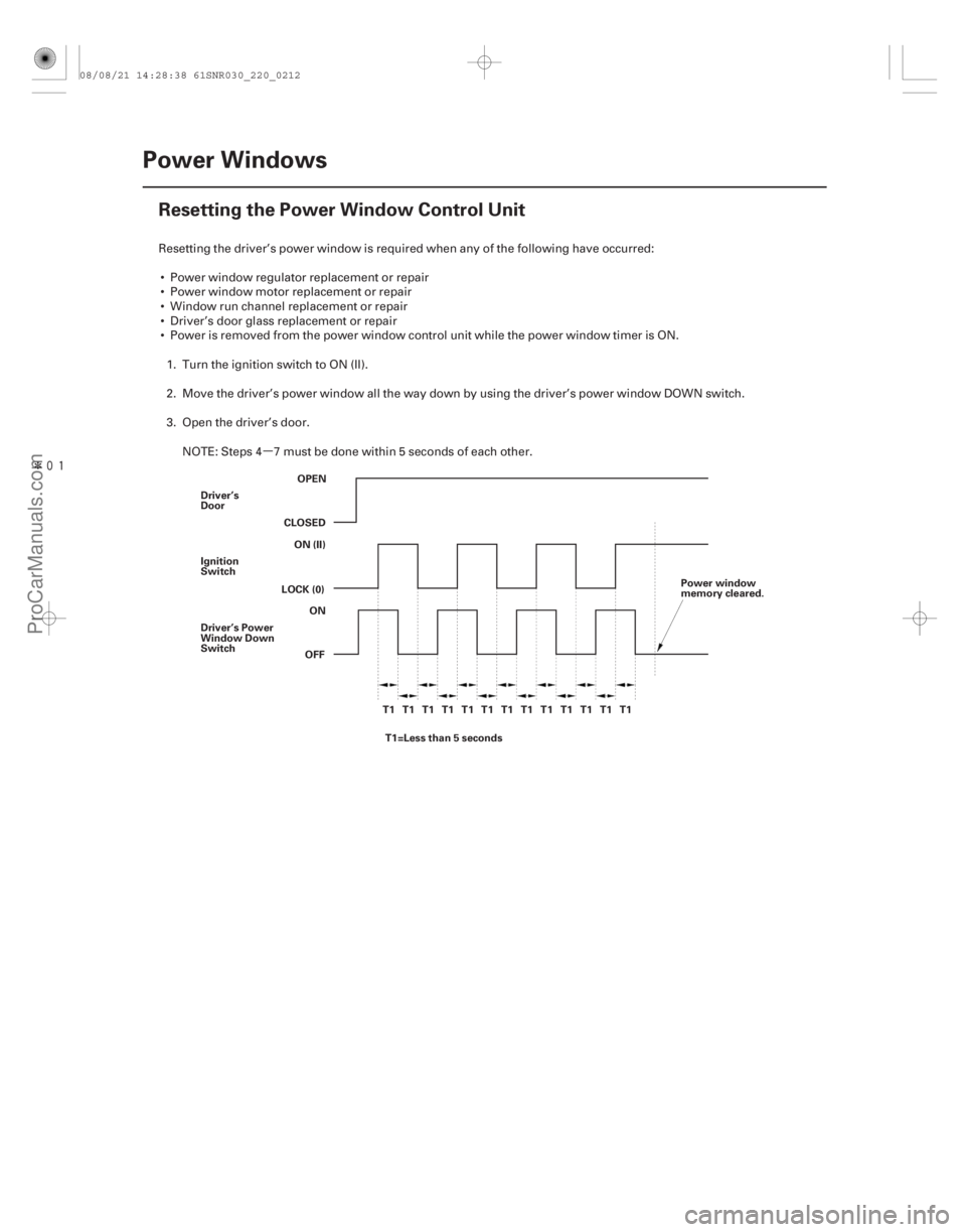
Resetting the Power Window Control Unit
OPEN
CLOSED ON (II)
LOCK (0)
OFFON
Driver’s
Door
Ignition
Switch
Driver’s Power
Window Down
Switch
T1 T1 T1 T1 T1 T1 T1 T1 T1 T1 T1 T1 T1T1=Less than 5 seconds Power window
memory cleared.
Resetting the driver’s power window is required when any of the following have occurred:
Power window regulator replacement or repair
Power window motor replacement or repair
Window run channel replacement or repair
Driver’s door glass replacement or repair
Power is removed from the power window control unit while the power window timer is ON. 1. Turn the ignition switch to ON (II).
2. Move the driver’s power window all the way down by using the driver’s power window DOWN switch.
3. Open the driver’s door.
NOTE: Steps 4 7 must be done within 5 seconds of each other.
08/08/21 14:28:38 61SNR030_220_0212
ProCarManuals.com
DYNOMITE -2009-
Page 2213 of 2893
����
�µ
�µ �µ
�µ
DTC B1155:
DTC B1156:
DTC B1159:
DTC B1188:
YES
NO YES
NO
22-263
Gauge Control Module Lost
Communication with the MICU (Headlight
Swi")
�(�#�'��������� �������������.�
�
�����������)����
�µ
�µ �µ
�µ
DTC B1155:
DTC B1156:
DTC B1159:
DTC B1188:
YES
NO YES
NO
22-263
Gauge Control Module Lost
Communication with the MICU (Headlight
Switch Message)
Gauge Control Module Lost
Communication with the MICU (Wiper Switch
Message)
Gauge Control Module Lost
Communication with the MICU (DOORSW
Message)
Gauge Control Module Lost
Communication with the MICU (RM
Message)
NOTE: If you are troubleshooting multiple DTCs, be
sure to follow the instructions in B-CAN System
Diagnosis Test Mode A (see page 22-93).
1. Clear the DTCs with the HDS.
2. Turn the ignition switch to LOCK (0), and then back to ON (II).
3. Check for DTCs with the HDS.
Go to step 4.
Intermittent failure. The gauge control
module is OK at this time. Check for loose or poor
connections. If the connections are good, check the
battery condition (see page 22-67), and the
charging system. 4. Check for DTCs with the HDS.
Faulty MICU; replace the under-dash fuse/
relay box (see page 22-66).
Replace the gauge control module (tach)
(see page 22-277).
Ar e DT Cs B115 5 , B115 6, 115 7 , B115 9, B1160, and / or B1188 i nd i cat ed ? Ar e DT Cs B115 5 , B115 6, 115 7 , B115 9, B1160,
and / or B1188 i nd i cat ed at t he same t i me?
08/08/21 14:35:19 61SNR030_220_0265
ProCarManuals.com
DYNOMITE -2009-
Page 2237 of 2893
����
22-287
Resetting the Moonroof Control Unit
Resetting the moonroof is required when any of the following have occurred: The moonroof was moved manual")
�(�#�'�������������������������������
�!�����)����
22-287
Resetting the Moonroof Control Unit
Resetting the moonroof is required when any of the following have occurred: The moonroof was moved manually while the battery was dead or disconnected.
The moonroof motor was replaced with a new one.
Any of components related to the moonroof were replaced. – Wind deflector
– Moonroof glass
– Moonroof seal
– Moonroof glass bracket
– Moonroof cables, etc.
To reset the moonroof control unit, do these steps: 1. Close the driver’s door, and keep it closed until the procedure is complete.
2. Turn the ignition switch to LOCK (0).
3. Press and hold the tilt switch, and turn the ignition switch to ON (II).
4. Release the tilt switch, and turn the ignition switch to LOCK (0).
5. Repeat steps 3 and 4 four times.
6. Press and hold the moonroof open switch for 3 additional seconds after the moonroof is fully opened.
7. Press and hold the moonroof close switch for 3 additional seconds after the moonroof is fully closed (tilted).
8. Confirm that the moonroof control unit is reset by using the moonroof AUTO OPEN and AUTO CLOSE function.
08/08/21 14:36:04 61SNR030_220_0289
ProCarManuals.com
DYNOMITE -2009-
Page 2274 of 2893
���
�µ
�µ
�µ
�µ �µ
�µ
�µ
�µ
Immobilizer indicator blinks
YES
NO
YES
NO YES
NO
YES
NO
22-324Immobilizer System
Symptom Troubleshooting (")
���
����
�(�#�'���������������������������������������)���
�µ
�µ
�µ
�µ �µ
�µ
�µ
�µ
Immobilizer indicator blinks
YES
NO
YES
NO YES
NO
YES
NO
22-324Immobilizer System
Symptom Troubleshooting (cont’d)
IMMOBILIZER-KEYLESS CONTROL UNIT 7P CONNECTOR
IG1 (YEL)
IMMOBILIZER-KEYLESS CONTROL UNIT 7P CONNECTOR LG (BLK)
NOTE: Before troubleshooting, check the items listed in
‘‘General Check before Troubleshooting’’.
1. Turn the ignition switch to LOCK (0).
2. Connect the HDS, then turn the ignition switch to ON (II).
3. Enter the IMMOBILIZER, then select the IMMOBILIZER SETUP.
4. Select the SYSTEM CHECK.
Troubleshoot the immob ilizer system
according to the result of the SYSTEM CHECK
(see page 22-326).
Go to step 5.
5. Turn the ignition switch to LOCK (0).
6. Enter the vehicle, and remove the ignition key from the ignition switch, then close the all doors.
7. Operate the keyless transmitter LOCK and UNLOCK several times in the vehicle.
Go to step 8.
Check for a poor ground (G 101) and/or an
open in the wire between immobilizer-keyless
control unit 7P connector terminal No. 7 and body
ground (G 101).
8. Turn the ignition switch to ON (II). 9. Measure the voltage between immobilizer-keyless
control unit 7P connector terminal No. 2 and body
ground.
Go to step 10.
Repair open in the YEL wire between the
under-dash fuse/relay box and the immob ilizer-
keyless control unit.
10. Measure the voltage between immobilizer-keyless control unit 7P connector terminal No. 7 and body
ground.
Repair poor connection or open between
immobilizer-keyless control unit 7P c onnector
terminal No. 7 and G101.
Replace the immobilizer-keyless control unit
(see page 22-332).
Wire side of female terminals
Wire side of female terminalsIs the SY ST EM CHECK indicated?
Do t he d oor l ock act uat or s w or k nor mal l y ? Is there battery voltage?
Is t her e 0.5 V or mor e?
08/08/21 14:37:00 61SNR030_220_0326
ProCarManuals.com
DYNOMITE -2009-