Page 272 of 508
4 - 37
ENG
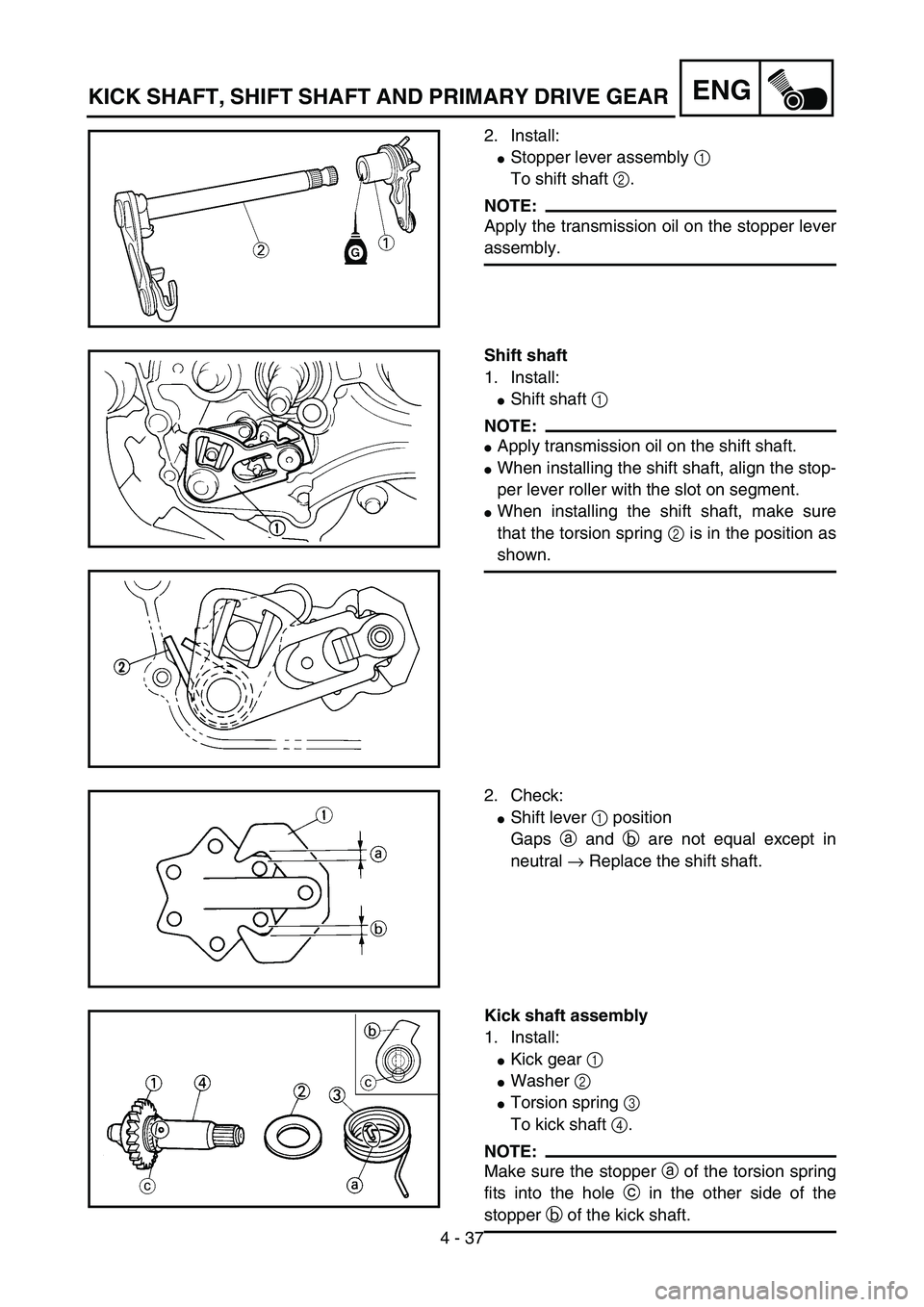
2. Install:
�Stopper lever assembly 1
To shift shaft 2.
NOTE:
Apply the transmission oil on the stopper lever
assembly.
5PA41070
Shift shaft
1. Install:
�Shift shaft 1
NOTE:
�Apply transmission oil on the shift shaft.
�When installing the shift shaft, align the stop-
per lever roller with the slot on segment.
�When installing the shift shaft, make sure
that the torsion spring 2 is in the position as
shown.
5PA41080
5PA41090
2. Check:
�Shift lever 1 position
Gaps a and b are not equal except in
neutral → Replace the shift shaft.
5PA41100
Kick shaft assembly
1. Install:
�Kick gear 1
�Washer 2
�Torsion spring 3
To kick shaft 4.
NOTE:
Make sure the stopper a of the torsion spring
fits into the hole c in the other side of the
stopper b of the kick shaft.
5PA41110
KICK SHAFT, SHIFT SHAFT AND PRIMARY DRIVE GEAR
Page 274 of 508
4 - 38
ENG
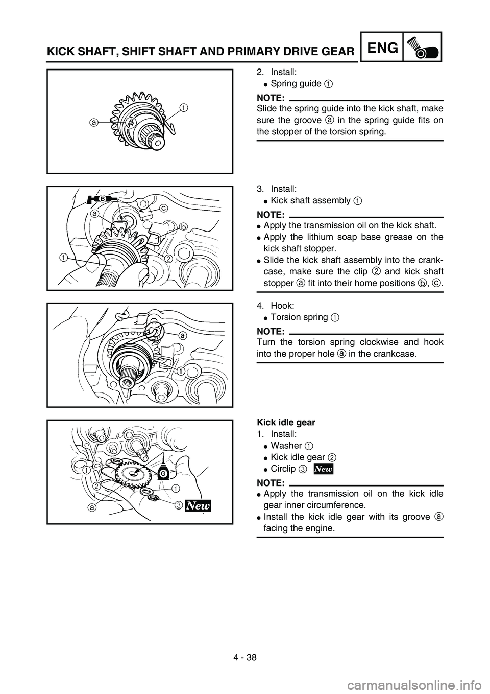
2. Install:
�Spring guide 1
NOTE:
Slide the spring guide into the kick shaft, make
sure the groove a in the spring guide fits on
the stopper of the torsion spring.
5PA41120
3. Install:
�Kick shaft assembly 1
NOTE:
�Apply the transmission oil on the kick shaft.
�Apply the lithium soap base grease on the
kick shaft stopper.
�Slide the kick shaft assembly into the crank-
case, make sure the clip 2 and kick shaft
stopper a fit into their home positions b, c.5PA41130
4. Hook:
�Torsion spring 1
NOTE:
Turn the torsion spring clockwise and hook
into the proper hole a in the crankcase.
5PA41140
Kick idle gear
1. Install:
�Washer 1
�Kick idle gear 2
�Circlip 3
NOTE:
�Apply the transmission oil on the kick idle
gear inner circumference.
�Install the kick idle gear with its groove a
facing the engine.
5PA41150
KICK SHAFT, SHIFT SHAFT AND PRIMARY DRIVE GEAR
Page 278 of 508
4 - 40
ENG
6. Install:
�Right crankcase cover 1
NOTE:
Mesh the impeller shaft gear 2 with primary
drive gear 3.
5PA41200
7. Install:
�Bolt (right crankcase cover) 1
�Copper washer (oil drain bolt) 2
�Oil drain bolt 3
�Copper washer (coolant drain bolt)
4
�Coolant drain bolt 5
NOTE:
Tighten the bolts in stage, using a crisscross
pattern.
5PA41210
T R..10 Nm (1.0 m · kg, 7.2 ft · lb)
T R..10 Nm (1.0 m · kg, 7.2 ft · lb)
T R..10 Nm (1.0 m · kg, 7.2 ft · lb)
8. Install:
�Kickstarter crank 1
�Washer 2
�Bolt (kickstarter crank) 3
NOTE:
Install the kickstarter crank closest to but not con-
tacting the pillar tube 4 and exhaust pipe 5.
5PA41220
T R..10 Nm (1.0 m · kg, 7.2 ft · lb)
9. Install:
�Shift pedal 1
�Bolt (shift pedal) 2
NOTE:
Install the shift pedal with the bottom of the
pedal outer diameter a as close to the center
of the engine mounting bolt 3 as possible.
5PA41230
T R..10 Nm (1.0 m · kg, 7.2 ft · lb)
KICK SHAFT, SHIFT SHAFT AND PRIMARY DRIVE GEAR
Page 280 of 508
4 - 41
ENG
EC4G0000
WATER PUMP
5PA41240
Extent of removal:
1 Impeller shaft removal
2 Oil seal removal
Extent of removal Order Part name Q’ty Remarks
WATER PUMP DISASSEMBLY
Preparation for removal Right crankcase cover Refer to “KICK SHAFT, SHIFT SHAFT
AND PRIMARY DRIVE GEAR” section.
1 Water pump housing 1
2 Impeller 1
Refer to “REMOVAL POINTS”. 3 Washer 1
4 Impeller shaft 1
5 Bearing 1
Refer to “REMOVAL POINTS”.
6 Oil seal 2
1
2
WATER PUMP
Page 282 of 508
4 - 42
ENG
REMOVAL POINTS
Impeller shaft
1. Remove:
�Impeller 1
�Washer 2
�Impeller shaft 3
NOTE:
Hold the impeller shaft on its width across the
flats a with spanners, etc. and remove the
impeller.
5PA41250
EC4G3210
Oil seal
NOTE:
�It is not necessary to disassemble the water
pump, unless there is an abnormality such
as excessive change in coolant level, discol-
oration of coolant, or milky transmission oil.
�Replace the oil seal whenever it is remov-
aled.
1. Remove:
�Bearing 1
2. Remove:
�Oil seal 1
5PA41260
5PA41270
INSPECTION
EC444200
Impeller shaft
1. Inspect:
�Impeller shaft 1
Bend/wear/damage → Replace.
Fur deposits → Clean.
5PA41280
WATER PUMP
Page 284 of 508
4 - 43
ENG
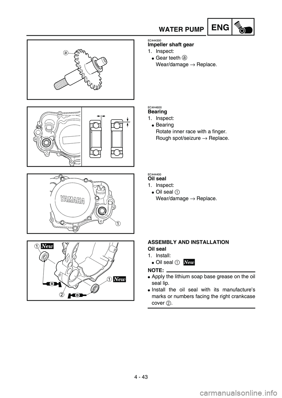
EC444300
Impeller shaft gear
1. Inspect:
�Gear teeth a
Wear/damage → Replace.
5PA41290
EC4H4600
Bearing
1. Inspect:
�Bearing
Rotate inner race with a finger.
Rough spot/seizure → Replace.
5PA41300
EC444400
Oil seal
1. Inspect:
�Oil seal 1
Wear/damage → Replace.
5PA41310
ASSEMBLY AND INSTALLATION
Oil seal
1. Install:
�Oil seal 1
NOTE:
�Apply the lithium soap base grease on the oil
seal lip.
�Install the oil seal with its manufacture’s
marks or numbers facing the right crankcase
cover 2.
5PA41320
WATER PUMP
Page 286 of 508
4 - 44
ENG
2. Install:
�Bearing 1
NOTE:
Install the bearing by pressing its outer race
parallel.
5PA41330
Impeller shaft
1. Install:
�Impeller shaft 1
�Washer 2
�Impeller 3
NOTE:
�Take care so that the oil seal lip is not dam-
aged or the spring does not slip off its posi-
tion.
�When installing the impeller shaft, apply the
lithium soap base grease on the oil seal lip
and impeller shaft. And install the shaft while
turning it.
�Hold the impeller shaft on its width across
the flats a with spanners, etc. and install the
impeller.
5PA41340
T R..14 Nm (1.4 m · kg, 10 ft · lb)
5PA41350
2. Install:
�Gasket (water pump housing) 1
5PA41360
3. Install:
�Water pump housing 1
�Bolt (water pump housing) 2
�Copper washer (coolant drain bolt)
3
�Coolant drain bolt 4
5PA41370
T R..10 Nm (1.0 m · kg, 7.2 ft · lb)
T R..10 Nm (1.0 m · kg, 7.2 ft · lb)
WATER PUMP
Page 304 of 508
4 - 53
ENG
CRANKCASE AND CRANKSHAFT
5PAR0009
Extent of removal:
1 Crankcase separation
2 Crankshaft removal
3 Crankshaft bearing removal
Extent of removal Order Part name Q’ty Remarks
CRANKCASE AND CRANK-
SHAFT REMOVAL
Preparation for removal Engine Refer to “ENGINE REMOVAL” section.
Piston Refer to “CYLINDER HEAD, CYLINDER
AND PISTON” section.
Primary drive gear
Refer to “KICK SHAFT, SHIFT SHAFT
AND PRIMARY DRIVE GEAR” section. Kick idle gear
Stopper lever assembly
Rotor and stator Refer to “CDI MAGNETO” section.
1 Screw (crankcase) 11
2 Crankcase oil seal holder 1
3 Right crankcase 1
Use special tool.
Refer to “REMOVAL POINTS”.
4 Left crankcase 1
5 Crankshaft 1 Use special tool.
Refer to “REMOVAL POINTS”.
6 Oil seal 2
7 Bearing 2 Refer to “REMOVAL POINTS”.
2
1
3
CRANKCASE AND CRANKSHAFT