Page 398 of 508

5 - 36
CHAS
19. Wait ten minutes until the air bubbles have
been removed from the front fork, and the
oil has dispense evenly in system before
setting recommended oil level.
NOTE:
Fill with the fork oil up to the top end of the
outer tube, or the fork oil will not spread over to
every part of the front forks, thus making it
impossible to obtain the correct level.
Be sure to fill with the fork oil up to the top of
the outer tube and bleed the front forks.
20. Measure:
�Oil level (left and right) a
Out of specification → Adjust.
NOTE:
Be sure to install the spring guide 2 when
checking the oil level.
WARNING
Never fail to make the oil level adjustment
between the maximum and minimum level
and always adjust each front fork to the
same setting. Uneven adjustment can
cause poor handling and loss of stability.
Standard oil level:
90 mm (3.54 in)
Extent of adjustment:
80 ~ 120 mm (3.15 ~ 4.72 in)
From top of outer tube with
inner tube and damper rod 1
fully compressed without
spring.
5PA51120
FRONT FORK
Page 412 of 508
5 - 43
CHAS
EC5B5000
ASSEMBLY AND INSTALLATION
Handlebar
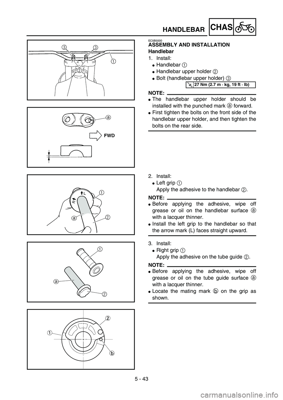
1. Install:
�Handlebar 1
�Handlebar upper holder 2
�Bolt (handlebar upper holder) 3
NOTE:
�The handlebar upper holder should be
installed with the punched mark a forward.
�First tighten the bolts on the front side of the
handlebar upper holder, and then tighten the
bolts on the rear side.
5PA51330
T R..27 Nm (2.7 m · kg, 19 ft · lb)
5PA51340
2. Install:
�Left grip 1
Apply the adhesive to the handlebar 2.
NOTE:
�Before applying the adhesive, wipe off
grease or oil on the handlebar surface a
with a lacquer thinner.
�Install the left grip to the handlebar so that
the arrow mark (L) faces straight upward.5PA51350
3. Install:
�Right grip 1
Apply the adhesive on the tube guide 2.
NOTE:
�Before applying the adhesive, wipe off
grease or oil on the tube guide surface a
with a lacquer thinner.
�Locate the mating mark b on the grip as
shown.5PA51360
5PA51370
HANDLEBAR
Page 430 of 508
5 - 52
CHAS
EC578000
SWINGARM DISASSEMBLY
5PAR0020
Extent of removal:
1 Swingarm disassembly
2 Connecting rod removal and disassembly
3 Relay arm removal and disassembly
Extent of removal Order Part name Q’ty Remarks
SWINGARM DISASSEMBLY
1 Relay arm 1
2 Connecting rod 1
3 Cover 2
4 Dust seal 2
5 Collar 5
6 Bushing 4
7 Oil seal 8
8 Bearing 9
Refer to “REMOVAL POINTS”.
9 Bushing (swingarm)
2
1
2
2
3
3
SWINGARM
Page 432 of 508
5 - 53
CHAS
EC573000
REMOVAL POINTS
Bearing and bushing
1. Remove:
�Bearing 1
�Bushing (swingarm) 2
From swingarm.
NOTE:
Remove the bushing by pressing.5PA51640
2. Remove:
�Bearing 1
From relay arm and connecting rod.
NOTE:
Remove the bearing by pressing its outer race.
5PAR0021
1
5PAR0022
INSPECTION
Wash the bearings, bushings, collars, and cov-
ers in a solvent.
Swingarm
1. Inspect:
�Bearing 1
�Bushing 2
�Collar 3
Free play exists/unsmooth revolution/rust
→ Replace bearing, bushing and collar as
a set.
2. Inspect:
�Oil seal 4
Damage → Replace.
5PA51680
SWINGARM
Page 434 of 508
 2
�Bushing 3
Free play exists/unsmooth revolution/rust
→ Replace bearing and bushing as a set.
2. Inspect:
�Bearing (polylu")
5 - 54
CHAS
Relay arm
1. Inspect:
�Bearing 1
�Bearing (polylube bearing) 2
�Bushing 3
Free play exists/unsmooth revolution/rust
→ Replace bearing and bushing as a set.
2. Inspect:
�Bearing (polylube bearing) 2
Loss of solid lubrication → Replace.
�Oil seal 4
Damage → Replace.
NOTE:
Polylube bearings, with solid lubrication, have
been adopted with the intent to make the nee-
dle bearings, used in this model, maintenance
free. With polylube bearings, no grease nipple
and regular lubrication is necessary. However,
grease should be applied to all oil seals and
collars when removed or installed.
Connecting rod
1. Inspect:
�Bearing 1
�Bushing 2
Free play exists/unsmooth revolution/rust
→ Replace bearing and bushing as a set.
2. Inspect:
�Oil seal 3
Damage → Replace.
5PAR0023
5PA51700
EC575000
ASSEMBLY AND INSTALLATION
Bearing, bushing and oil seal
1. Install:
�Bearing 1
�Bushing (swingarm) 2
�Oil seal 3
To swingarm.
NOTE:
�Apply the molybdenum disulfide grease on
the bearing and bushing when installing.
�Install the bearing by pressing it on the side
having the manufacture’s marks or numbers.
�First install the bushing and then the bearing
to a specified depth from inside.
Installed depth of bearings and
bushings:
Bearing a: 4.5 mm (0.18 in)
Bushing b: 4.5 mm (0.18 in)
5PA51730
5PA51740
SWINGARM
Page 436 of 508
5 - 55
CHAS
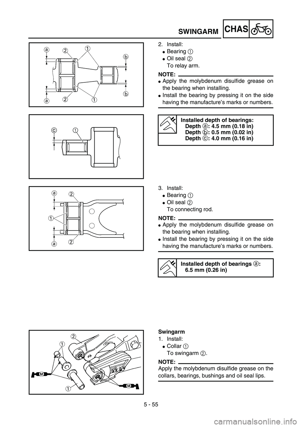
2. Install:
�Bearing 1
�Oil seal 2
To relay arm.
NOTE:
�Apply the molybdenum disulfide grease on
the bearing when installing.
�Install the bearing by pressing it on the side
having the manufacture’s marks or numbers.
Installed depth of bearings:
Depth a: 4.5 mm (0.18 in)
Depth b: 0.5 mm (0.02 in)
Depth c: 4.0 mm (0.16 in)
5PA51750
5PA51760
c1
3. Install:
�Bearing 1
�Oil seal 2
To connecting rod.
NOTE:
�Apply the molybdenum disulfide grease on
the bearing when installing.
�Install the bearing by pressing it on the side
having the manufacture’s marks or numbers.
Installed depth of bearings a:
6.5 mm (0.26 in)
5PA51760
Swingarm
1. Install:
�Collar 1
To swingarm 2.
NOTE:
Apply the molybdenum disulfide grease on the
collars, bearings, bushings and oil seal lips.
5PA51770
SWINGARM
Page 438 of 508
5 - 56
CHAS
2. Install:
�Bushing 1
�Collar 2
�Dust seal 3
�Cover 4
To relay arm 5.
NOTE:
Apply the molybdenum disulfide grease on the
bushings, dust seals, collars, cover lips, bear-
ings and oil seal lips.
3. Install:
�Bushing 1
To connecting rod 2.
NOTE:
Apply the molybdenum disulfide grease on the
bushings, bearings and oil seal lips.
5PAR0025
5PA51790
4. Install:
�Connecting rod 1
�Washer 2
�Bolt (connecting rod) 3
�Nut (connecting rod) 4
To swingarm 5.
NOTE:
Apply the molybdenum disulfide grease on the
bolt.
5PA51800
T R..53 Nm (5.3 m · kg, 38 ft · lb)
5. Install:
�Relay arm 1
�Bolt (relay arm) 2
�Nut (relay arm) 3
NOTE:
Apply the molybdenum disulfide grease on the
bolt.
5PA51810
T R..54 Nm (5.4 m · kg, 39 ft · lb)
SWINGARM
Page 444 of 508

5 - 59
CHAS
HANDLING NOTE
WARNING
This rear shock absorber is provided with a
separate type tank filled with high-pressure
nitrogen gas. To prevent the danger of
explosion, read and understand the follow-
ing information before handling the shock
absorber.
The manufacturer can not be held respon-
sible for property damage or personal
injury that may result from improper han-
dling.
1. Never tamper or attempt to disassem-
ble the cylinder or the tank.
2. Never throw the rear shock absorber
into an open flame or other high heat.
The rear shock absorber may explode
as a result of nitrogen gas expansion
and/or damage to the hose.
3. Be careful not to damage any part of
the gas tank. A damaged gas tank will
impair the damping performance or
cause a malfunction.
4. Take care not to scratch the contact
surface of the piston rod with the cylin-
der; or oil could leak out.
5. Never attempt to remove the plug at
the bottom of the nitrogen gas tank. It
is very dangerous to remove the plug.
6. When scrapping the rear shock
absorber, follow the instructions on
disposal.
NOTES ON DISPOSAL (YAMAHA DEALERS
ONLY)
Before disposing the rear shock absorber, be
sure to extract the nitrogen gas from valve 1.
Wear eye protection to prevent eye damage
from escaping gas and/or metal chips.
WARNING
To dispose of a damaged or worn-out rear
shock absorber, take the unit to your
Yamaha dealer for this disposal procedure.
5PA51880
REAR SHOCK ABSORBER