Page 172 of 508

3 - 25
INSP
ADJFRONT FORK OIL SEAL AND DUST SEAL CLEANING/
FRONT FORK INTERNAL PRESSURE BLEEDING/
FRONT FORK REBOUND DAMPING FORCE ADJUSTMENT
EC36D001
FRONT FORK OIL SEAL AND DUST SEAL
CLEANING
1. Remove:
�Protector 1
�Dust seal 2
NOTE:
Use a thin screw driver, and be careful not to
damage the inner fork tube and dust seal.5PA30580
2. Clean:
�Dust seal a
�Oil seal b
NOTE:
�Clean the dust seal and oil seal after every
run.
�Apply the lithium soap base grease on the
inner tube.
5PA30590
FRONT FORK INTERNAL PRESSURE
BLEEDING
NOTE:
If the front fork initial movement feels stiff dur-
ing a run, bleed the front fork internal pressure.
1. Elevate the front wheel by placing a suit-
able stand under the engine.
2. Remove the air bleed screw 1 and release
the internal pressure from the front fork.
3. Install:
�Air bleed screw
EC36H002
FRONT FORK REBOUND DAMPING FORCE
ADJUSTMENT
1. Adjust:
�Rebound damping force
By turning the adjuster 1.
Stiffer a → Increase the rebound damp-
ing force. (Turn the adjuster 1 in.)
Softer b → Decrease the rebound damp-
ing force. (Turn the adjuster 1 out.)
5PA30590
T R..1 Nm (0.1 m · kg, 0.7 ft · lb)
5PA30600
Page 178 of 508

3 - 28
INSP
ADJREAR SHOCK ABSORBER SPRING PRELOAD
ADJUSTMENT
REAR SHOCK ABSORBER SPRING
PRELOAD ADJUSTMENT
1. Elevate the rear wheel by placing the suit-
able stand under the engine.
2. Remove:
�Rear frame
3. Loosen:
�Locknut 1
4. Adjust:
�Spring preload
By turning the adjuster 2.
* For EUROPE
NOTE:
�Be sure to remove all dirt and mud from
around the locknut and adjuster before
adjustment.
�The length of the spring (installed) changes
1.5 mm (0.06 in) per turn of the adjuster.
CAUTION:
Never attempt to turn the adjuster beyond
the maximum or minimum setting.
5. Tighten:
�Locknut
6. Install:
�Rear frame (upper)
�Rear frame (lower) Stiffer
→Increase the spring preload.
(Turn the adjuster
2 in.)
Softer
→Decrease the spring preload.
(Turn the adjuster
2 out.)
Spring length (installed)
a:
YZ85: 215 mm (8.46 in)
*212 mm (8.35 in)
YZ85LW: 207 mm (8.15 in)
*212 mm (8.35 in)
Extent of adjustment:
202.5 ~ 218.5 mm
(7.97 ~ 8.60 in)
5PA30630
5PA30640
T R..26 Nm (2.6 m · kg, 19 ft · lb)
T R..16 Nm (1.6 m · kg, 11 ft · lb)
Page 186 of 508
3 - 32
INSP
ADJ
EC36T000
WHEEL INSPECTION
1. Inspect:
�Wheel runout
Elevate the wheel and turn it.
Abnormal runout → Replace.
5PA30700
2. Inspect:
�Bearing free play
Exist play → Replace.
5PA30710
STEERING HEAD INSPECTION AND
ADJUSTMENT
1. Elevate the front wheel by placing a suit-
able stand under the engine.
2. Check:
�Steering stem
Grasp the bottom of the forks and gently
rock the fork assembly back and forth.
Free play → Adjust steering head.
3. Check:
�Steering smooth action
Turn the handlebar lock to lock.
Unsmooth action → Adjust steering ring
nut.
5PA30720
5PA30730
WHEEL INSPECTION/
STEERING HEAD INSPECTION AND ADJUSTMENT
Page 290 of 508
4 - 46
ENG
EC4L3000
REMOVAL POINTS
Rotor
1. Remove:
�Nut (rotor) 1
�Washer 2
Use the rotor holding tool 3.
Rotor holding tool:
YU-1235/90890-01235
5PA41390
2. Remove:
�Rotor 1
Use the flywheel puller 2.
NOTE:
When installing the flywheel puller, turn it
counterclockwise.
Flywheel puller:
YM-1189/90890-01189
5PA41400
EC4L4000
INSPECTION
EC4L4101
CDI magneto
1. Inspect:
�Rotor inner surface a
�Stator outer surface b
Damage → Inspect the crankshaft runout
and crankshaft bearing.
If necessary, replace CDI magneto and/or
stator.
5PA41410
EC4L4200
Woodruff key
1. Inspect:
�Woodruff key 1
Damage → Replace.
5PA41420
CDI MAGNETO
Page 322 of 508
4 - 62
ENG
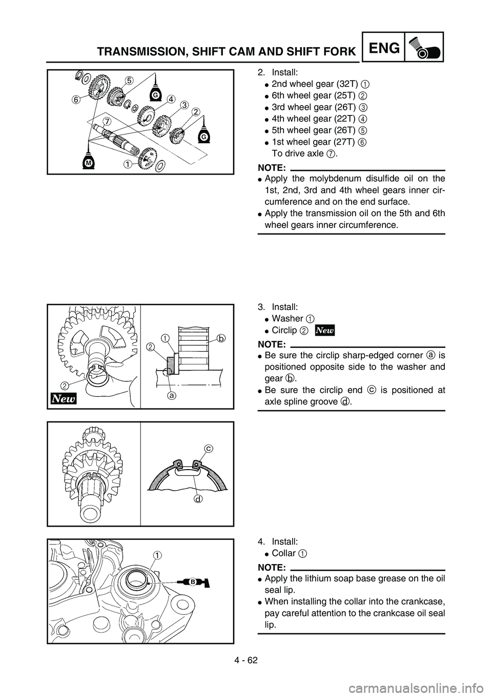
2. Install:
�2nd wheel gear (32T) 1
�6th wheel gear (25T) 2
�3rd wheel gear (26T) 3
�4th wheel gear (22T) 4
�5th wheel gear (26T) 5
�1st wheel gear (27T) 6
To drive axle 7.
NOTE:
�Apply the molybdenum disulfide oil on the
1st, 2nd, 3rd and 4th wheel gears inner cir-
cumference and on the end surface.
�Apply the transmission oil on the 5th and 6th
wheel gears inner circumference.
5PA41880
3. Install:
�Washer 1
�Circlip 2
NOTE:
�Be sure the circlip sharp-edged corner a is
positioned opposite side to the washer and
gear b.
�Be sure the circlip end c is positioned at
axle spline groove d.
5PA41900
5PA41890
4. Install:
�Collar 1
NOTE:
�Apply the lithium soap base grease on the oil
seal lip.
�When installing the collar into the crankcase,
pay careful attention to the crankcase oil seal
lip.
5PAR0011
TRANSMISSION, SHIFT CAM AND SHIFT FORK
Page 324 of 508
4 - 63
ENG
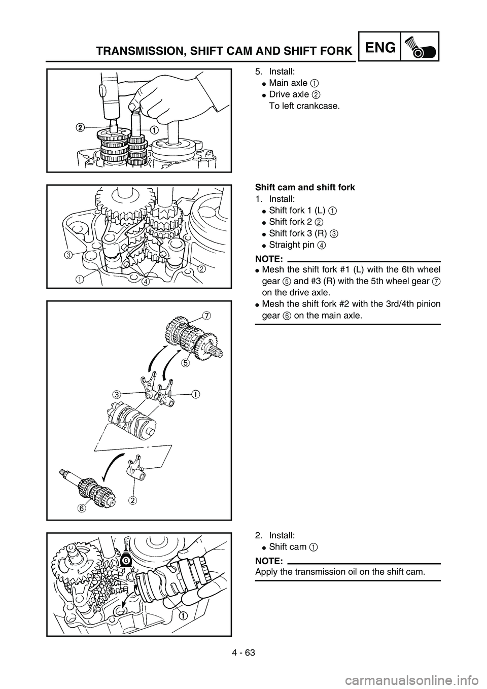
5. Install:
�Main axle 1
�Drive axle 2
To left crankcase.
5PA41920
Shift cam and shift fork
1. Install:
�Shift fork 1 (L) 1
�Shift fork 2 2
�Shift fork 3 (R) 3
�Straight pin 4
NOTE:
�Mesh the shift fork #1 (L) with the 6th wheel
gear 5 and #3 (R) with the 5th wheel gear 7
on the drive axle.
�Mesh the shift fork #2 with the 3rd/4th pinion
gear 6 on the main axle.
5PA41930
5PA41940
2. Install:
�Shift cam 1
NOTE:
Apply the transmission oil on the shift cam.
5PA41950
TRANSMISSION, SHIFT CAM AND SHIFT FORK
Page 328 of 508
5 - 1
CHAS
EC500000
CHASSIS
EC590000
FRONT WHEEL AND REAR WHEEL
EC598000
FRONT WHEEL
FRONT WHEEL AND REAR WHEEL
Extent of removal:
1 Front wheel removal
2 Wheel bearing removal
3 Brake disc removal
Extent of removal Order Part name Q’ty Remarks
Preparation for removalFRONT WHEEL REMOVAL
Hold the machine by placing the
suitable stand under the engine.
WARNING
Support the machine securely so there is nodanger of it falling over.
1 Nut (front wheel axle) 1
2 Front wheel axle 1
3 Front wheel 1
4 Collar 2
5 Oil seal 2
6 Bearing 2 Refer to “REMOVAL POINTS”.
7 Brake disc 1
2
31
3
5PA50010
Page 330 of 508
5 - 2
CHAS
EC598100
REAR WHEEL
5PAR0012
Extent of removal:
1 Rear wheel removal
2 Wheel bearing removal
3 Brake disc removal
Extent of removal Order Part name Q’ty Remarks
Preparation for removalREAR WHEEL REMOVAL
Hold the machine by placing the
suitable stand under the engine.
WARNING
Support the machine securely so there is no
danger of it falling over.
1 Nut (rear wheel axle) 1
2 Rear wheel axle 1
3 Drive chain puller 2
4 Rear wheel 1 Refer to “REMOVAL POINTS”.
5 Collar 2
6 Rear wheel sprocket 1
7 Oil seal 2
8 Circlip 1
9 Bearing 2 Refer to “REMOVAL POINTS”.
10Brake disc
1
2
31
3
FRONT WHEEL AND REAR WHEEL