Page 332 of 508
5 - 3
CHAS
EC593000
REMOVAL POINTS
EC523101
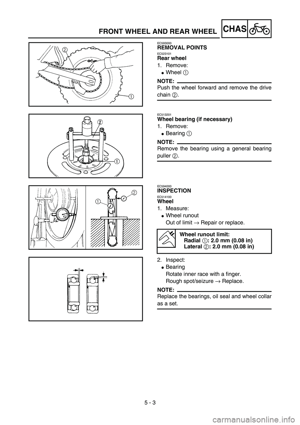
Rear wheel
1. Remove:
�Wheel 1
NOTE:
Push the wheel forward and remove the drive
chain 2.
5PA50030
EC513201
Wheel bearing (if necessary)
1. Remove:
�Bearing 1
NOTE:
Remove the bearing using a general bearing
puller 2.
5PA50040
EC594000
INSPECTION
EC514100
Wheel
1. Measure:
�Wheel runout
Out of limit → Repair or replace.
2. Inspect:
�Bearing
Rotate inner race with a finger.
Rough spot/seizure → Replace.
NOTE:
Replace the bearings, oil seal and wheel collar
as a set.
Wheel runout limit:
Radial 1: 2.0 mm (0.08 in)
Lateral 2: 2.0 mm (0.08 in)
5PA50050
5PA50060
FRONT WHEEL AND REAR WHEEL
Page 334 of 508
5 - 4
CHAS
EC514200
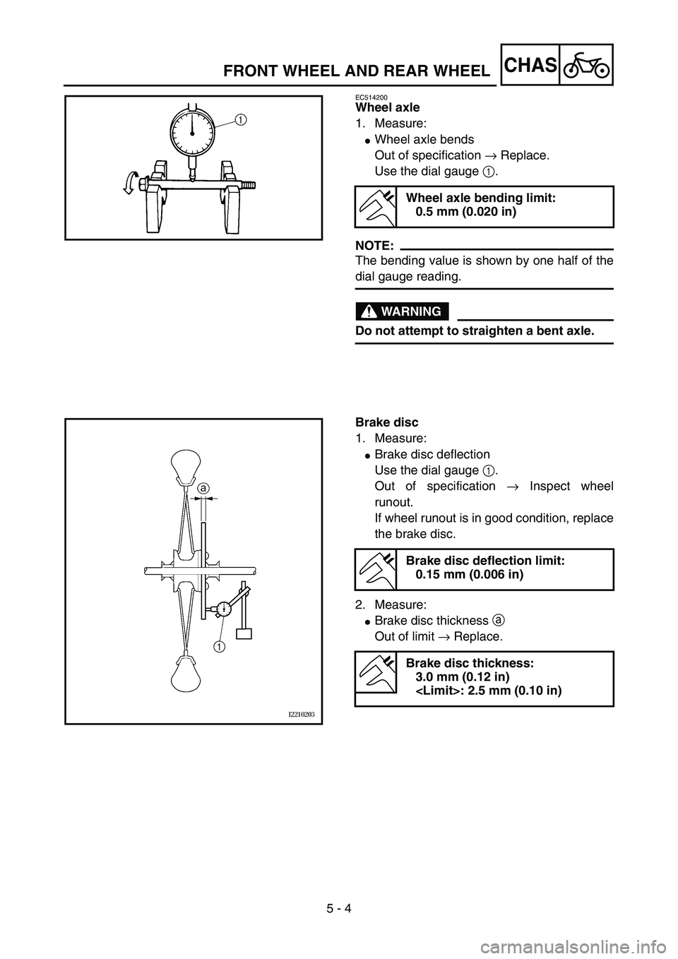
Wheel axle
1. Measure:
�Wheel axle bends
Out of specification → Replace.
Use the dial gauge 1.
NOTE:
The bending value is shown by one half of the
dial gauge reading.
WARNING
Do not attempt to straighten a bent axle.
Wheel axle bending limit:
0.5 mm (0.020 in)
5PA50070
Brake disc
1. Measure:
�Brake disc deflection
Use the dial gauge 1.
Out of specification → Inspect wheel
runout.
If wheel runout is in good condition, replace
the brake disc.
2. Measure:
�Brake disc thickness a
Out of limit → Replace.
Brake disc deflection limit:
0.15 mm (0.006 in)
Brake disc thickness:
3.0 mm (0.12 in)
: 2.5 mm (0.10 in)
5PA50080
FRONT WHEEL AND REAR WHEEL
Page 336 of 508
5 - 5
CHAS
EC595000
ASSEMBLY AND INSTALLATION
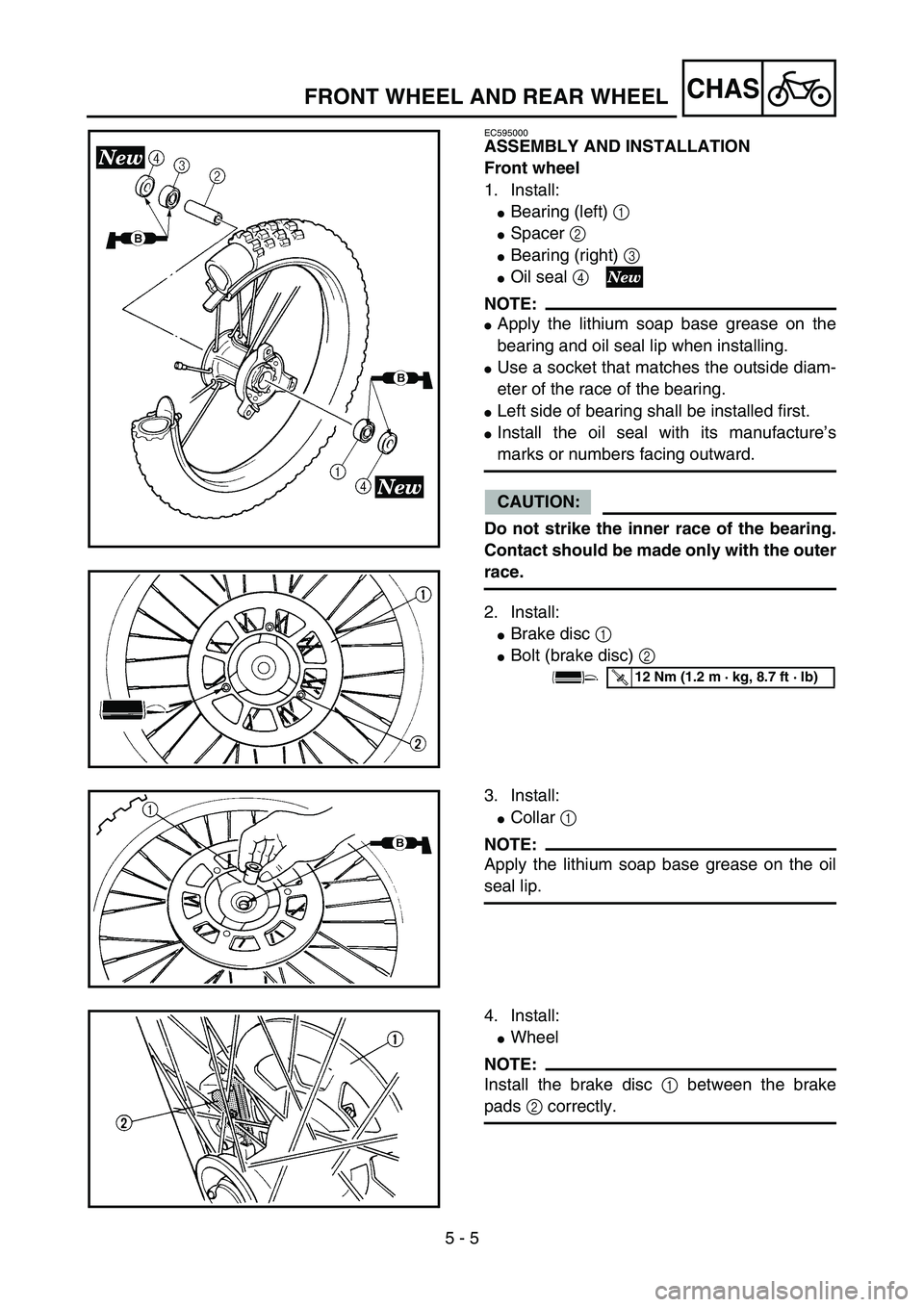
Front wheel
1. Install:
�Bearing (left) 1
�Spacer 2
�Bearing (right) 3
�Oil seal 4
NOTE:
�Apply the lithium soap base grease on the
bearing and oil seal lip when installing.
�Use a socket that matches the outside diam-
eter of the race of the bearing.
�Left side of bearing shall be installed first.
�Install the oil seal with its manufacture’s
marks or numbers facing outward.
CAUTION:
Do not strike the inner race of the bearing.
Contact should be made only with the outer
race.
2. Install:
�Brake disc 1
�Bolt (brake disc) 2
5PA50090
5PA50100
T R..12 Nm (1.2 m · kg, 8.7 ft · lb)
3. Install:
�Collar 1
NOTE:
Apply the lithium soap base grease on the oil
seal lip.
5PA50110
4. Install:
�Wheel
NOTE:
Install the brake disc 1 between the brake
pads 2 correctly.
5PA50120
FRONT WHEEL AND REAR WHEEL
Page 338 of 508
5 - 6
CHAS
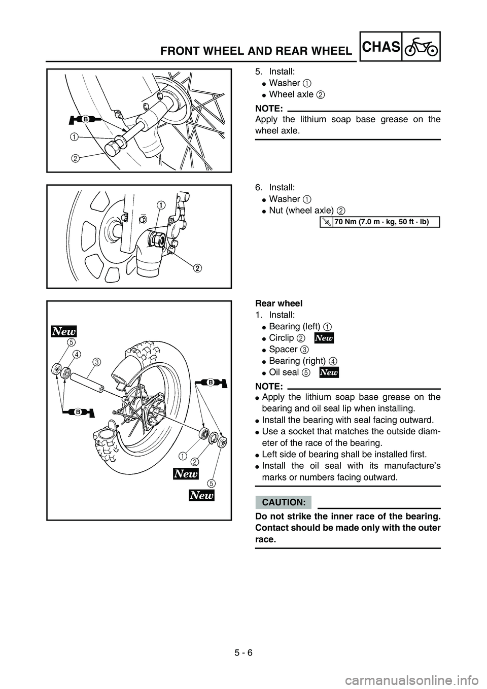
5. Install:
�Washer 1
�Wheel axle 2
NOTE:
Apply the lithium soap base grease on the
wheel axle.
5PA50130
6. Install:
�Washer 1
�Nut (wheel axle) 2
5PA50140
T R..70 Nm (7.0 m · kg, 50 ft · lb)
Rear wheel
1. Install:
�Bearing (left) 1
�Circlip 2
�Spacer 3
�Bearing (right) 4
�Oil seal 5
NOTE:
�Apply the lithium soap base grease on the
bearing and oil seal lip when installing.
�Install the bearing with seal facing outward.
�Use a socket that matches the outside diam-
eter of the race of the bearing.
�Left side of bearing shall be installed first.
�Install the oil seal with its manufacture’s
marks or numbers facing outward.
CAUTION:
Do not strike the inner race of the bearing.
Contact should be made only with the outer
race.
5PA50150
FRONT WHEEL AND REAR WHEEL
Page 340 of 508
5 - 7
CHAS
2. Install:
�Brake disc 1
�Bolt (brake disc) 2
NOTE:
Tighten the bolts (brake disc) in stage, using a
crisscross pattern.
5PA50160
T R..12 Nm (1.2 m · kg, 8.7 ft · lb)
3. Install:
�Rear wheel sprocket 1
�Bolt (rear wheel sprocket) 2
�Washer (rear wheel sprocket) 3
�Nut (rear wheel sprocket) 4
NOTE:
Tighten the nuts (rear wheel sprocket) in
stage, using a crisscross pattern.5PA50170
T R..42 Nm (4.2 m · kg, 30 ft · lb)
4. Install:
�Collar 1
NOTE:
Apply the lithium soap base grease on the oil
seal lip.
5PA50180
5. Install:
�Wheel
NOTE:
Install the brake disc 1 between the brake
pads 2 correctly.
5PA50190
6. Install:
�Drive chain 1
NOTE:
Push the wheel 2 forward and install the drive
chain.
5PA50200
FRONT WHEEL AND REAR WHEEL
Page 342 of 508
5 - 8
CHAS
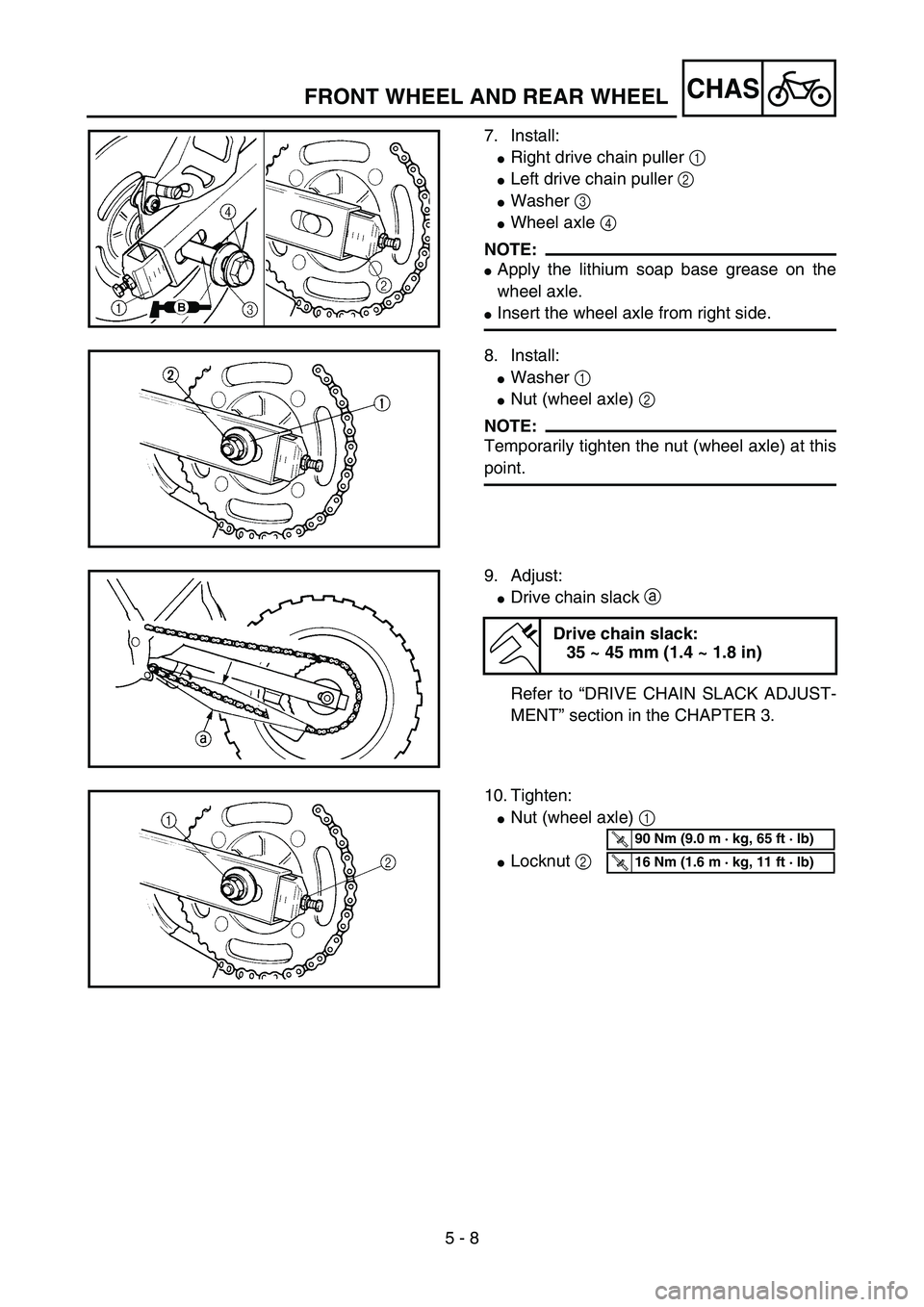
7. Install:
�Right drive chain puller 1
�Left drive chain puller 2
�Washer 3
�Wheel axle 4
NOTE:
�Apply the lithium soap base grease on the
wheel axle.
�Insert the wheel axle from right side.5PAR0013
8. Install:
�Washer 1
�Nut (wheel axle) 2
NOTE:
Temporarily tighten the nut (wheel axle) at this
point.
5PAR0014
9. Adjust:
�Drive chain slack a
Refer to “DRIVE CHAIN SLACK ADJUST-
MENT” section in the CHAPTER 3.
Drive chain slack:
35 ~ 45 mm (1.4 ~ 1.8 in)
5PA50230
10. Tighten:
�Nut (wheel axle) 1
�Locknut 2
5PAR0015
T R..90 Nm (9.0 m · kg, 65 ft · lb)
T R..16 Nm (1.6 m · kg, 11 ft · lb)
FRONT WHEEL AND REAR WHEEL
Page 380 of 508
5 - 27
CHASFRONT FORK
EC550000
FRONT FORK
5PA50820
Extent of removal:
1 Front fork removal
Extent of removal Order Part name Q’ty Remarks
Preparation for removalFRONT FORK REMOVAL
Hold the machine by placing the
suitable stand under the engine.
WARNING
Support the machine securely so there is no
danger of it falling over.
Front wheel Refer to “FRONT WHEEL AND REAR
WHEEL” section.
Front brake caliper Refer to “FRONT BRAKE AND REAR
BRAKE” section.
Number plate
Handlebar Refer to “HANDLEBAR” section.
1 Protector 1
2 Brake hose holder 1
3 Pinch bolt (upper bracket) 1 Only loosening.
4 Cap bolt 1 Loosen when disassembling the front fork.
5 Pinch bolt (lower bracket) 2 Only loosening.
6 Front fork 1
1
Page 428 of 508
5 - 51
CHASSWINGARM
EC570000
SWINGARM
5PAR0019
Extent of removal:
1 Swingarm removal
Extent of removal Order Part name Q’ty Remarks
SWINGARM REMOVAL
WARNING
Support the machine securely so there is no
danger of it falling over.
Preparation for removal Hold the machine by placing the
suitable stand under the engine.
Real wheel Refer to “FRONT WHEEL AND REAR
WHEEL” section.
Brake hose holder
Rear brake caliper
Drive chainRefer to “FRONT BRAKE AND REAR
BRAKE” section.
1 Drive chain support 1
2 Bolt (connecting rod) 1 Hold the swingarm.
3 Bolt (rear shock absorber-relay
arm)1
4 Pivot shaft 1
5 Swingarm 1
1