2005 YAMAHA YZ250F check
[x] Cancel search: checkPage 606 of 668

–+ELEC
6 - 7
THROTTLE POSITION SENSOR SYSTEM
THROTTLE POSITION SENSOR SYSTEM
INSPECTION STEPS
If the throttle position sensor will not operate, use the following inspection steps.
* marked: Refer to “IGNITION SYSTEM” section.
NOTE:
Use the following special tools in this inspection.
Pocket tester:
YU-3112-C/90890-03112
Check entire ignition
system for connection.Repair or replace.
Check throttle position
sensor.Throttle posi-
tion sensor coilReplace.
*Check CDI magneto. Charging coil Replace.
Check CDI unit.Throttle posi-
tion sensor
input voltageReplace.
OK
OK
OK
No good
No good
No good
No good
Page 610 of 668

6 - 8
–+ELECTHROTTLE POSITION SENSOR SYSTEM
HANDLING NOTE
CAUTION:
Do not loosen the screws (throttle position
sensor)
1 except when changing the throt-
tle position sensor due to failure because it
will cause a drop in engine performance.
1
EC624000
COUPLERS AND LEADS CONNECTION
INSPECTION
1. Check:
Couplers and leads connection
Rust/dust/looseness/short-circuit →
Repair or replace.
THROTTLE POSITION SENSOR COIL
INSPECTION
1. Inspect:
Throttle position sensor coil resistance
Out of specification → Replace.
Tester (+) lead
→ Blue lead
1
Tester (–) lead
→ Black lead
2
Throttle posi-
tion sensor coil
resistanceTester selector
position
4 ~ 6 kΩ at
20 °C (68 °F)kΩ × 1
2. Loosen:
Throttle stop screw 1
NOTE:
Turn out the throttle stop screw until the throt-
tle shaft is in the full close position.
Page 612 of 668

6 - 9
–+ELECTHROTTLE POSITION SENSOR SYSTEM
3. Inspect:
Throttle position sensor coil variable
resistance
Check that the resistance in increased as
the throttle grip is moved from the full
close position to the full open position.
Out of specification → Replace.
Tester (+) lead
→ Yellow lead
1
Tester (–) lead
→ Black lead
2
Throttle position sen-
sor coil variable
resistanceTester
selector
position
Full
closedFull
opened
k
Ω
× 1
Zero ~ 3 k
Ω
at 20 °C
(68°F)4 ~ 6 k
Ω at
20 °C
(68°F)
THROTTLE POSITION SENSOR
REPLACEMENT AND ADJUSTMENT
1. Remove:
Throttle position sensor coupler
Screw (throttle position sensor) 1
Throttle position sensor 2
NOTE:
Loosen the screws (throttle position sensor)
using the T25 bit.
2. Replace:
Throttle position sensor
12
3. Install:
Throttle position sensor 1
Screw (throttle position sensor) 2
NOTE:
Align the slot a in the throttle position sensor
with the projection b on the carburetor.
Temporarily tighten the screws (throttle posi-
tion sensor).
21
b
a
Page 618 of 668

7 - 1
TUN
EC700000
TUNING
EC710000
ENGINE
Carburetor setting
The air/fuel mixture will vary depending on
atmospheric conditions. Therefore, it is nec-
essary to take into consideration the air pres-
sure, ambient temperature, humidity, etc.,
when adjusting the carburetor.
Perform a test run to check for proper engine
performance (e.g., throttle response) and
spark plug(-s) discoloration or fouling. Use
these readings to determine the best possi-
ble carburetor setting.
NOTE:
It is recommended to keep a record of all car-
buretor settings and external conditions (e.g.,
atmospheric conditions, track/surface condi-
tions, lap times) to make future carburetor set-
ting easier.
WARNING
The carburetor is a part of the fuel line.
Therefore, be sure to install it in a well-
ventilated area, away from flammable
objects and any sources of fire.
Never look into the carburetor intake.
Flames may shoot out from the pipe if the
engine backfires while it is being started.
Gasoline may be discharged from the
accelerator pump nozzle when the carbu-
retor has been removed.
SETTING
Page 620 of 668
7 - 2
TUN
CAUTION:
The carburetor is extremely sensitive to
foreign matter (dirt, sand, water, etc.).
During installation, do not allow foreign
matter to get into the carburetor.
Always handle the carburetor and its
components carefully. Even slight
scratches, bends or damage to carburetor
parts may prevent the carburetor from
functioning correctly. Carefully perform
all servicing with the appropriate tools
and without applying excessive force.
When the engine is stopped or when
riding at no load, do not open and close
the throttle unnecessarily. Otherwise, too
much fuel may be discharged, starting
may become difficult or the engine may
not run well.
After installing the carburetor, check that
the throttle operates correctly and opens
and closes smoothly.
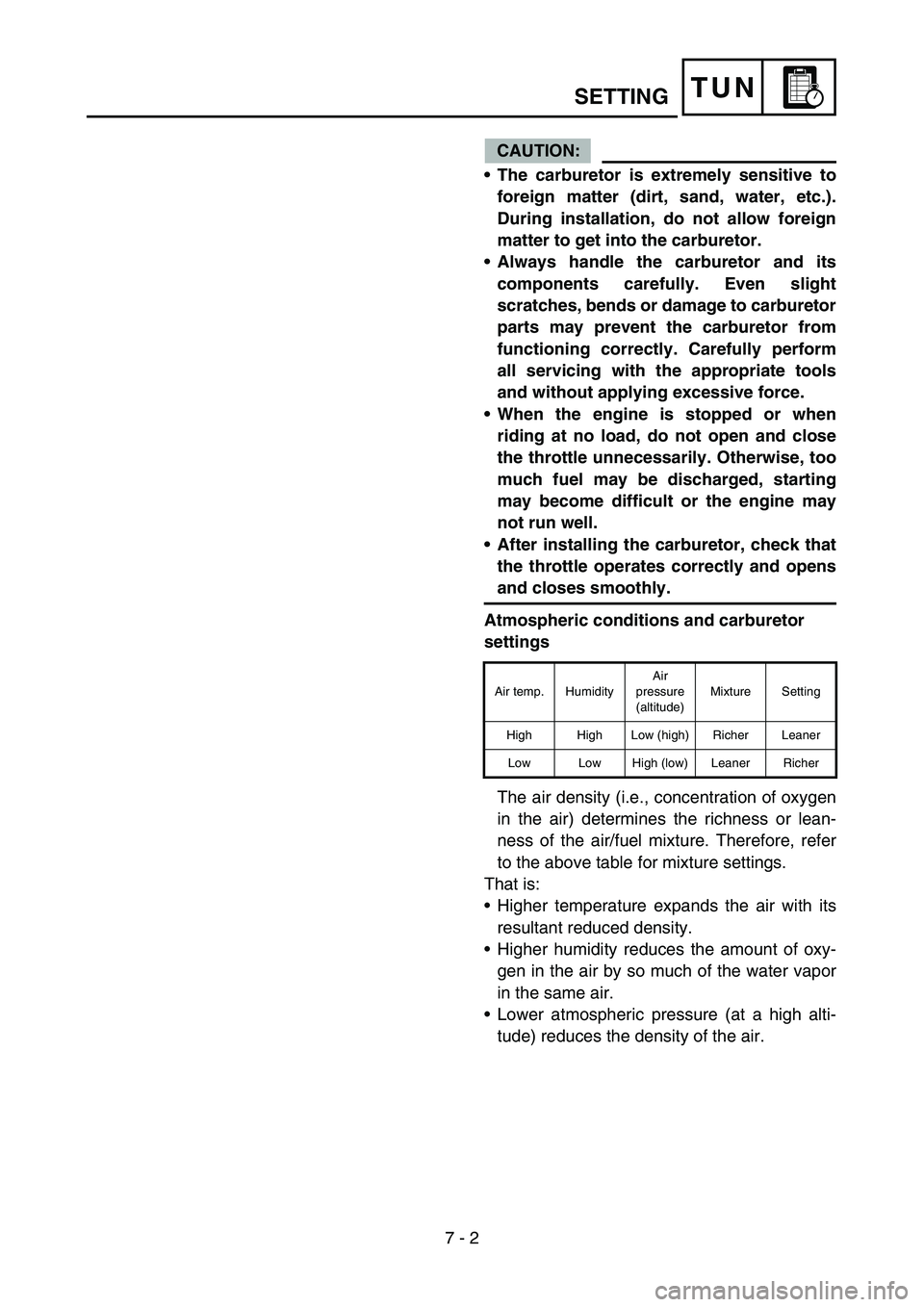
Atmospheric conditions and carburetor
settings
The air density (i.e., concentration of oxygen
in the air) determines the richness or lean-
ness of the air/fuel mixture. Therefore, refer
to the above table for mixture settings.
That is:
Higher temperature expands the air with its
resultant reduced density.
Higher humidity reduces the amount of oxy-
gen in the air by so much of the water vapor
in the same air.
Lower atmospheric pressure (at a high alti-
tude) reduces the density of the air.
Air temp. HumidityAir
pressure
(altitude)Mixture Setting
High High Low (high) Richer Leaner
Low Low High (low) Leaner Richer
SETTING
Page 636 of 668
7 - 10
TUN
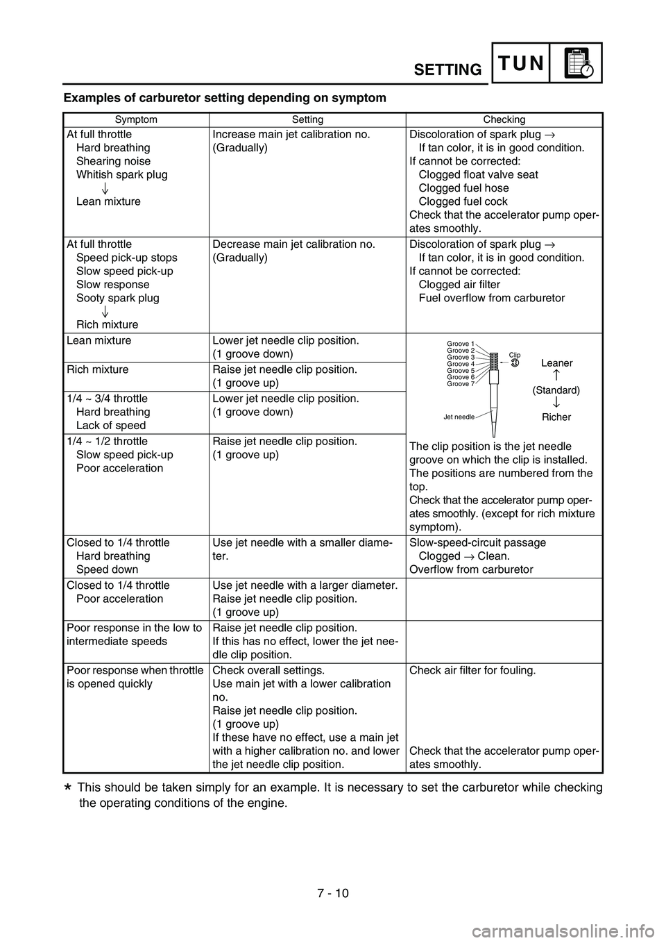
Examples of carburetor setting depending on symptom
This should be taken simply for an example. It is necessary to set the carburetor while checking
the operating conditions of the engine.
Symptom Setting Checking
At full throttle
Hard breathing
Shearing noise
Whitish spark plug
Lean mixtureIncrease main jet calibration no.
(Gradually)Discoloration of spark plug
→
If tan color, it is in good condition.
If cannot be corrected:
Clogged float valve seat
Clogged fuel hose
Clogged fuel cock
Check that the accelerator pump oper-
ates smoothly.
At full throttle
Speed pick-up stops
Slow speed pick-up
Slow response
Sooty spark plug
Rich mixtureDecrease main jet calibration no.
(Gradually)Discoloration of spark plug
→
If tan color, it is in good condition.
If cannot be corrected:
Clogged air filter
Fuel overflow from carburetor
Lean mixture Lower jet needle clip position.
(1 groove down)
The clip position is the jet needle
groove on which the clip is installed.
The positions are numbered from the
top.
Check that the accelerator pump oper-
ates smoothly. (except for rich mixture
symptom). Rich mixture Raise jet needle clip position.
(1 groove up)
1/4 ~ 3/4 throttle
Hard breathing
Lack of speedLower jet needle clip position.
(1 groove down)
1/4 ~ 1/2 throttle
Slow speed pick-up
Poor accelerationRaise jet needle clip position.
(1 groove up)
Closed to 1/4 throttle
Hard breathing
Speed downUse jet needle with a smaller diame-
ter.Slow-speed-circuit passage
Clogged
→ Clean.
Overflow from carburetor
Closed to 1/4 throttle
Poor accelerationUse jet needle with a larger diameter.
Raise jet needle clip position.
(1 groove up)
Poor response in the low to
intermediate speedsRaise jet needle clip position.
If this has no effect, lower the jet nee-
dle clip position.
Poor response when throttle
is opened quicklyCheck overall settings.
Use main jet with a lower calibration
no.
Raise jet needle clip position.
(1 groove up)
If these have no effect, use a main jet
with a higher calibration no. and lower
the jet needle clip position.Check air filter for fouling.
Check that the accelerator pump oper-
ates smoothly.
Jet needleClip
Groove 7 Groove 6
Groove 5
Groove 4
Groove 3
Groove 2
Groove 1
Leaner
↑
(Standard)
↓
Richer
*
SETTING
Page 658 of 668

7 - 20
TUNSETTING
EC72H002
Suspension setting
Front fork
NOTE:
If any of the following symptoms is experienced with the standard position as the base, make
resetting by reference to the adjustment procedure given in the same chart.
Before any change, set the rear shock absorber sunken length to the standard figure 90 ~ 100 mm
(3.5 ~ 3.9 in).
SymptomSection
Check Adjust
JumpLarge
gapMedium
gapSmall
gap
Stiff over entire rangeCompression damping Turn adjuster counterclockwise (about 2 clicks) to
decrease damping.
Oil amount Decrease oil amount by about 5 ~ 10 cm
3 (0.2 ~
0.4 Imp oz, 0.2 ~ 0.3 US oz).
Spring Replace with soft spring.
Unsmooth movement
over entire rangeOuter tube Check for any bends, dents, and other noticeable
scars, etc. If any, replace affected parts.
Inner tube
Slide metal Replace with a new one for extended use.
Piston metal Replace with a new one for extended use.
Under bracket tightening
torqueRetighten to specified torque.
Poor initial
movementRebound damping Turn adjuster counterclockwise (about 2 clicks) to
decrease damping.
Oil seal Apply grease in oil seal wall.
Soft over entire
range, bottoming outCompression damping Turn adjuster clockwise (about 2 clicks) to increase
damping.
Oil amount Increase oil amount by about 5 ~ 10 cm
3 (0.2 ~ 0.4
Imp oz, 0.2 ~ 0.3 US oz).
Spring Replace with stiff spring.
Stiff toward stroke
endOil amountDecrease oil amount by about 5 cm
3 (0.2 Imp oz,
0.2 US oz).
Soft toward stroke
end, bottoming outOil amountIncrease oil amount by about 5 cm
3 (0.2 Imp oz,
0.2 US oz).
Stiff initial movement Compression dampingTurn adjuster counterclockwise (about 2 clicks) to
decrease damping.
Low front, tending to
lower front postureCompression damping Turn adjuster clockwise (about 2 clicks) to increase
damping.
Rebound damping Turn adjuster counterclockwise (about 2 clicks) to
decrease damping.
Balance with rear end Set sunken length for 95 ~ 100 mm (3.7 ~ 3.9 in)
when one passenger is astride seat (lower rear pos-
ture).
Oil amount Increase oil amount by about 5 cm
3 (0.2 Imp oz,
0.2 US oz).
“Obtrusive” front,
tending to upper front
postureCompression damping Turn adjuster counterclockwise (about 2 clicks) to
decrease damping.
Balance with rear end Set sunken length for 90 ~ 95 mm (3.5 ~ 3.7 in)
when one passenger is astride seat (upper rear pos-
ture).
Spring Replace with soft spring.
Oil amount Decrease oil amount by about 5 ~ 10 cm
3 (0.2 ~ 0.4
Imp oz, 0.2 ~ 0.3 US oz).
Page 659 of 668

7 - 21
TUNSETTING
Rear shock absorber
NOTE:
If any of the following symptoms is experienced with the standard position as the base, make
resetting by reference to the adjustment procedure given in the same chart.
Adjust the rebound damping in 2-click increments or decrements.
Adjust the low compression damping in 1-click increments or decrements.
Adjust the high compression damping in 1/6 turn increments or decrements.
SymptomSection
Check Adjust
JumpLarge
gapMedium
gapSmall
gap
Stiff, tending to sinkRebound damping Turn adjuster counterclockwise (about 2 clicks) to
decrease damping.
Spring set length Set sunken length for 90 ~ 100 mm (3.5 ~ 3.9 in)
when one passenger is astride seat.
Spongy and unstableRebound damping Turn adjuster clockwise (about 2 clicks) to increase
damping.
Low compression damp-
ingTurn adjuster clockwise (about 1 click) to increase
damping.
Spring Replace with stiff spring.
Heavy and draggingRebound damping Turn adjuster counterclockwise (about 2 clicks) to
decrease damping.
Spring Replace with soft spring.
Poor road grippingRebound damping Turn adjuster counterclockwise (about 2 clicks) to
decrease damping.
Low compression damp-
ingTurn adjuster clockwise (about 1 clicks) to increase
damping.
High compression damp-
ingTurn adjuster clockwise (about 1/6 clicks) to
increase damping.
Spring set length Set sunken length for 90 ~ 100 mm (3.5 ~ 3.9 in)
when one passenger is astride seat.
Spring Replace with soft spring.
Bottoming outHigh compression damp-
ingTurn adjuster clockwise (about 1/6 turn) to increase
damping.
Spring set length Set sunken length for 90 ~ 100 mm (3.5 ~ 3.9 in)
when one passenger in astride seat.
Spring Replace with stiff spring.
BouncingRebound damping Turn adjuster clockwise (about 2 clicks) to increase
damping.
Spring Replace with soft spring.
Stiff travelHigh compression damp-
ingTurn adjuster counterclockwise (about 1/6 turn) to
decrease damping.
Spring set length Set sunken length for 90 ~ 100 mm (3.5 ~ 3.9 in)
when one passenger is astride seat.
Spring Replace with soft spring.