Page 306 of 668
4 - 26
ENGCAMSHAFTS
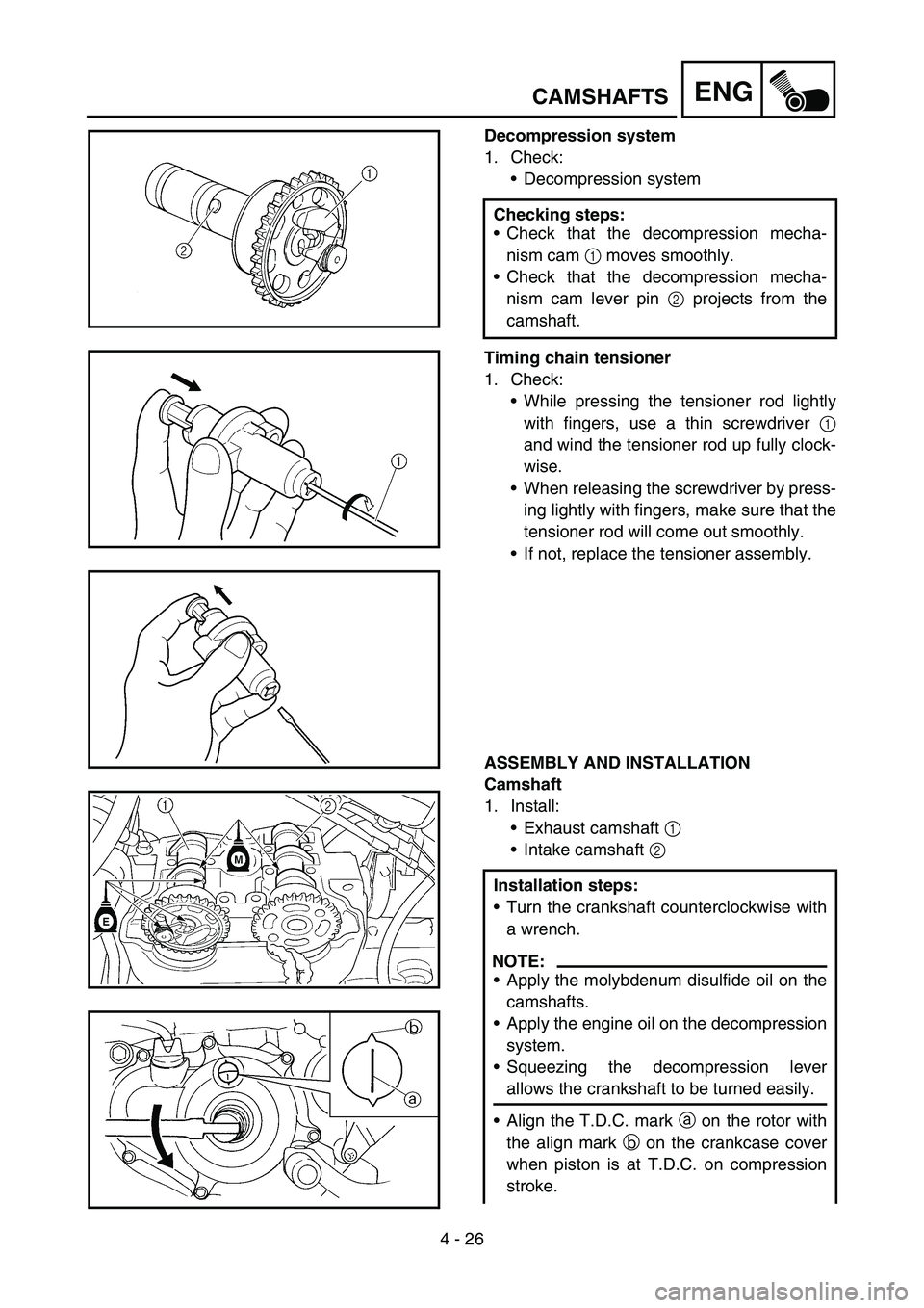
Decompression system
1. Check:
Decompression system
Timing chain tensioner
1. Check:
While pressing the tensioner rod lightly
with fingers, use a thin screwdriver 1
and wind the tensioner rod up fully clock-
wise.
When releasing the screwdriver by press-
ing lightly with fingers, make sure that the
tensioner rod will come out smoothly.
If not, replace the tensioner assembly.
ASSEMBLY AND INSTALLATION
Camshaft
1. Install:
Exhaust camshaft 1
Intake camshaft 2 Checking steps:
Check that the decompression mecha-
nism cam 1 moves smoothly.
Check that the decompression mecha-
nism cam lever pin 2 projects from the
camshaft.
Installation steps:
Turn the crankshaft counterclockwise with
a wrench.
NOTE:
Apply the molybdenum disulfide oil on the
camshafts.
Apply the engine oil on the decompression
system.
Squeezing the decompression lever
allows the crankshaft to be turned easily.
Align the T.D.C. mark a on the rotor with
the align mark b on the crankcase cover
when piston is at T.D.C. on compression
stroke.
Page 310 of 668
4 - 28
ENG
With the rod fully wound and the chain ten-
sioner UP mark a facing upward, install
the gasket 1 and the timing chain ten-
sioner 2, and tighten the bolt 3 to the
specified torque.
T R..
Bolt (timing chain tensioner):
10 Nm (1.0 m kg, 7.2 ft lb)
Release the screwdriver, check the ten-
sioner rod to come out and tighten the
gasket 4 and the cap bolt 5 to the speci-
fied torque.
T R..
Tensioner cap bolt:
7 Nm (0.7 m kg, 5.1 ft lb)
5
4
3. Turn:
Crankshaft
Counterclockwise several turns.
4. Check:
Rotor T.D.C. mark
Align with the crankcase align mark.
Camshaft match marks
Align with the cylinder head surface.
Out of alignment → Adjust.
5. Install:
Timing mark accessing screw 1
Crankshaft end accessing screw 2
CAMSHAFTS
Page 322 of 668
4 - 34
ENGVALVES AND VALVE SPRINGS
REMOVAL POINTS
Valve lifter and valve cotter
1. Remove:
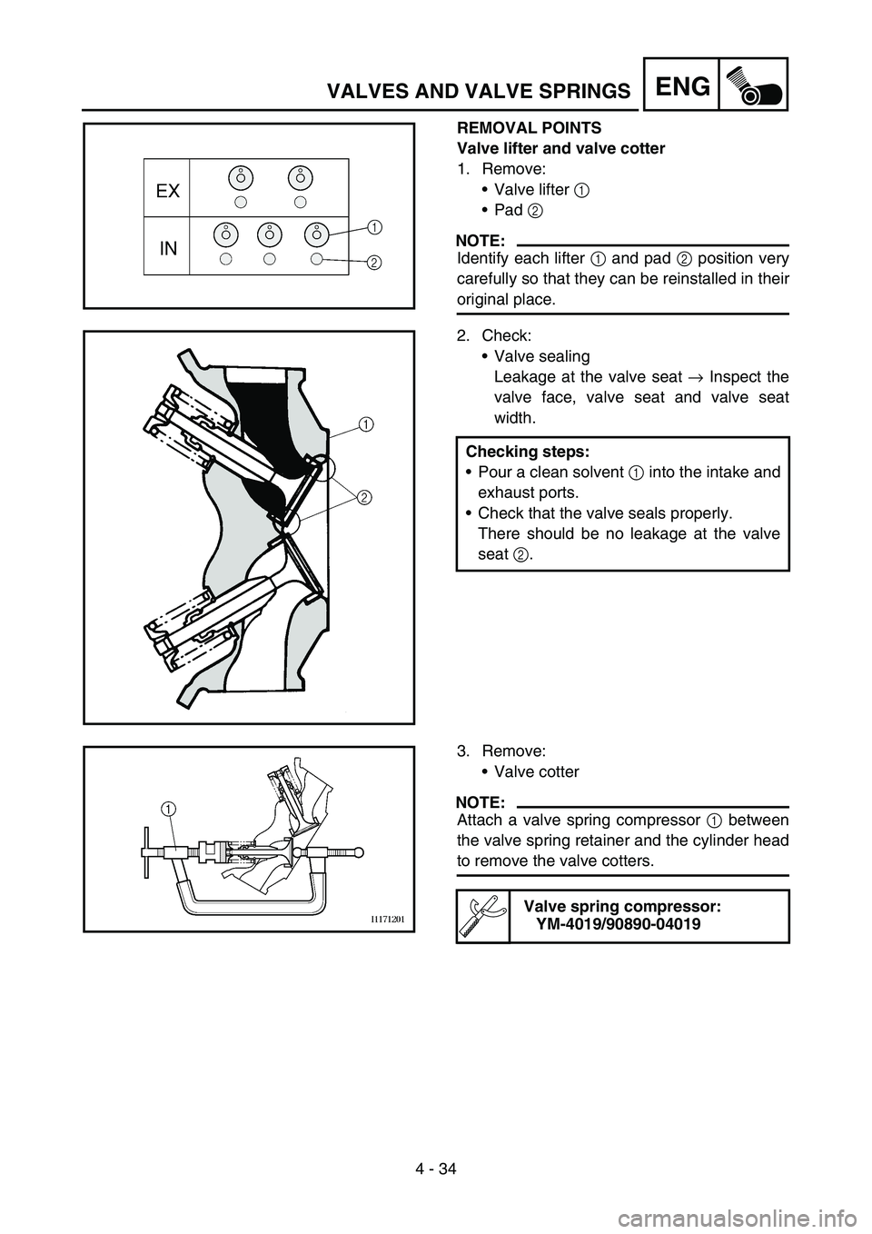
Valve lifter 1
Pad 2
NOTE:
Identify each lifter 1 and pad 2 position very
carefully so that they can be reinstalled in their
original place.
2. Check:
Valve sealing
Leakage at the valve seat → Inspect the
valve face, valve seat and valve seat
width.
Checking steps:
Pour a clean solvent 1 into the intake and
exhaust ports.
Check that the valve seals properly.
There should be no leakage at the valve
seat 2.
3. Remove:
Valve cotter
NOTE:
Attach a valve spring compressor 1 between
the valve spring retainer and the cylinder head
to remove the valve cotters.
Valve spring compressor:
YM-4019/90890-04019
Page 356 of 668
4 - 51
ENGCLUTCH
EC4A3000
REMOVAL POINTS
Clutch boss
1. Remove:
Nut 1
Lock washer 2
Clutch boss 3
NOTE:
Straighten the lock washer tab and use the
clutch holding tool 4 to hold the clutch boss.
È
For USA and CDN
ÉExcept for USA and CDN
Clutch holding tool:
YM-91042/90890-04086
È
É
EC4A4000
INSPECTION
EC484100
Clutch housing and boss
1. Inspect:
Clutch housing 1
Cracks/wear/damage → Replace.
Clutch boss 2
Scoring/wear/damage → Replace.
EC484201
Primary driven gear
1. Check:
Circumferential play
Free play exists → Replace.
Gear teeth a
Wear/damage → Replace.
Clutch spring
1. Measure:
Clutch spring free length a
Out of specification → Replace springs
as a set.
Clutch spring free length:
40.4 mm (1.59 in)
: 39.4 mm (1.55 in)
Page 390 of 668
4 - 68
ENGOIL PUMP
INSPECTION
Oil pump
1. Inspect:
Oil pump drive gear 1
Oil pump drive shaft 2
Rotor housing 3
Oil pump cover 4
Cracks/wear/damage → Replace.
1
32
4
2. Measure:
Tip clearance a
(between the inner rotor 1 and outer
rotor 2)
Side clearance b
(between the outer rotor 2 and rotor
housing 3)
Housing and rotor clearance c
(between the rotor housing 3 and rotors
1 2)
Out of specification → Replace the oil
pump assembly.
Tip clearance a:
0.12 mm or less
(0.0047 in or less)
: 0.20 mm (0.008 in)
Side clearance b:
0.09 ~ 0.17 mm
(0.0035 ~ 0.0067 in)
: 0.24 mm (0.009 in)
Housing and rotor clearance c:
0.03 ~ 0.10 mm
(0.0012 ~ 0.0039 in)
: 0.17 mm (0.0067 in)
3. Check:
Unsmooth → Repeat steps #1 and #2 or
replace the defective parts.
Page 400 of 668
4 - 73
ENGKICK SHAFT AND SHIFT SHAFT
REMOVAL POINTS
Kick shaft assembly
1. Remove:
Kick shaft assembly 1
NOTE:
Unhook the torsion spring 2 from the hole a
in the crankcase.
EC4C3101
Shift guide and shift lever assembly
1. Remove:
Bolt (shift guide)
Shift guide 1
Shift lever assembly 2
NOTE:
The shift lever assembly is disassembled at
the same time as the shift guide.
EC4N3100
Segment
1. Remove:
Bolt (segment) 1
Segment 2
NOTE:
Turn the segment counterclockwise until it
stops and loosen the bolt.
INSPECTION
Kick shaft and ratchet wheel
1. Check:
Ratchet wheel 1 smooth movement
Unsmooth movement → Replace.
Kick shaft 2
Wear/damage → Replace.
Spring 3
Broken → Replace.
EC4C4300
Kick gear, kick idle gear and ratchet wheel
1. Inspect:
Kick gear 1
Kick idle gear 2
Ratchet wheel 3
Gear teeth a
Ratchet teeth b
Wear/damage → Replace.
Page 434 of 668
4 - 90
ENGCRANKCASE AND CRANKSHAFT
REMOVAL POINTS
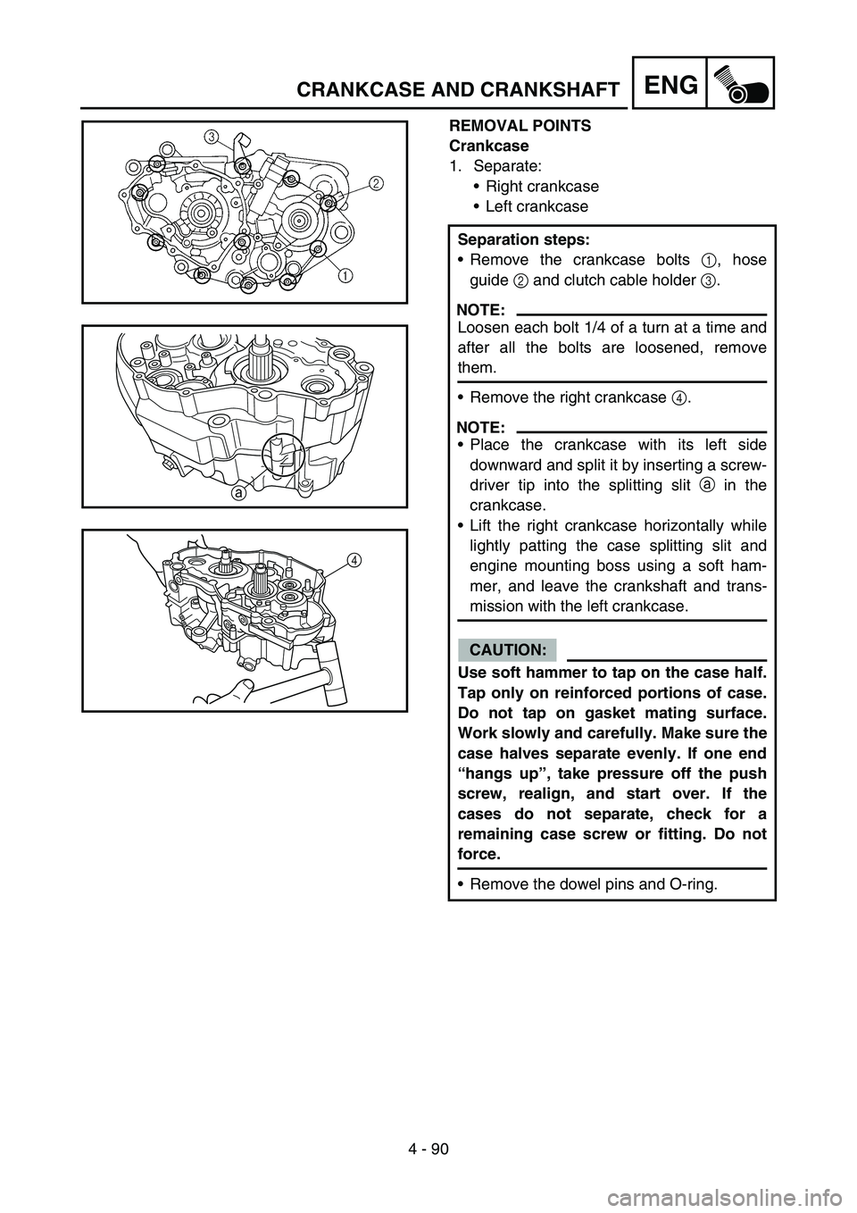
Crankcase
1. Separate:
Right crankcase
Left crankcase
Separation steps:
Remove the crankcase bolts 1, hose
guide 2 and clutch cable holder 3.
NOTE:
Loosen each bolt 1/4 of a turn at a time and
after all the bolts are loosened, remove
them.
Remove the right crankcase 4.
NOTE:
Place the crankcase with its left side
downward and split it by inserting a screw-
driver tip into the splitting slit a in the
crankcase.
Lift the right crankcase horizontally while
lightly patting the case splitting slit and
engine mounting boss using a soft ham-
mer, and leave the crankshaft and trans-
mission with the left crankcase.
CAUTION:
Use soft hammer to tap on the case half.
Tap only on reinforced portions of case.
Do not tap on gasket mating surface.
Work slowly and carefully. Make sure the
case halves separate evenly. If one end
“hangs up”, take pressure off the push
screw, realign, and start over. If the
cases do not separate, check for a
remaining case screw or fitting. Do not
force.
Remove the dowel pins and O-ring.
a
4
Page 442 of 668
4 - 94
ENGCRANKCASE AND CRANKSHAFT
2. Check:
Shifter operation
Transmission operation
Unsmooth operation → Repair.
3. Install:
Oil strainer 1
Bolt (oil strainer) 2
T R..10 Nm (1.0 m · kg, 7.2 ft · lb)
4. Apply:
Sealant
On the right crankcase 1.
NOTE:
Clean the contacting surface of left and right
crankcase before applying the sealant.
5. Install:
Dowel pin 1
O-ring 2
Right crankcase
To left crankcase.
NOTE:
Fit the right crankcase onto the left crank-
case. Tap lightly on the case with soft ham-
mer.
When installing the crankcase, the connect-
ing rod should be positioned at TDC (top
dead center).
Quick gasket®:
ACC-QUICK-GS-KT
YAMAHA Bond No. 1215:
90890-85505