Page 49 of 82
PERIODIC MAINTENANCE AND MINOR REPAIR
6-10
6 6. Check the final gear case for oil
leakage. If oil is leaking, check for
the cause.
EAU20670
Cleaning the air filter element The air filter element should be cleaned
as follows at the intervals specified in
the periodic maintenance and lubrica-
tion chart. Clean the air filter element
more frequently if you are riding in un-
usually wet or dusty areas.
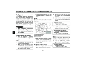
1. Remove the air filter case cover by
removing the screws.
2. Pull the air filter element out.
3. Lightly tap the air filter element to
remove most of the dust and dirt,
and then blow the remaining dirt
out with compressed air as shown.
If the air filter element is damaged,
replace it.4. Insert the air filter element into the
air filter case as shown.1. Air filter case cover
2. Screw
1. Air filter element
2. Projection
3. Slot
U5YSE0E0.book Page 10 Tuesday, June 8, 2004 2:04 PM
Page 50 of 82

PERIODIC MAINTENANCE AND MINOR REPAIR
6-11
6
CAUTION:
ECA10480
�
Make sure that the air filter ele-
ment is properly seated in the
air filter case.
�
The engine should never be op-
erated without the air filter ele-
ment installed, otherwise the
piston(s) and/or cylinder(s) maybecome excessively worn.
5. Install the air filter case cover by in-
stalling the screws.
EAU21290
Adjusting the carburetors The carburetors are important parts of
the engine and require very sophisticat-
ed adjustment. Therefore, most carbu-
retor adjustments should be left to a
Yamaha dealer, who has the neces-
sary professional knowledge and expe-
rience. The adjustment described in the
following section, however, may be ser-
viced by the owner as part of routine
maintenance.CAUTION:
ECA10560
The carburetors have been set and
extensively tested at the Yamaha
factory. Changing these settings
without sufficient technical knowl-
edge may result in poor perfor-mance of or damage to the engine.
EAU21340
Adjusting the engine idling
speed The engine idling speed must be
checked and, if necessary, adjusted as
follows at the intervals specified in the
periodic maintenance and lubrication
chart.
The engine should be warm before
making this adjustment.NOTE:�
The engine is warm when it quickly
responds to the throttle.
�
A diagnostic tachometer is neededto make this adjustment.
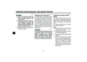
1. Attach the tachometer to the spark
plug lead.
2. Check the engine idling speed
and, if necessary, adjust it to spec-
ification by turning the throttle stop
screw. To increase the engine
idling speed, turn the screw in di-
rection (a). To decrease the en-
gine idling speed, turn the screw in
direction (b).
U5YSE0E0.book Page 11 Tuesday, June 8, 2004 2:04 PM
Page 51 of 82
PERIODIC MAINTENANCE AND MINOR REPAIR
6-12
6
NOTE:
If the specified idling speed cannot be
obtained as described above, have aYamaha dealer make the adjustment.
EAU21380
Adjusting the throttle cable
free play The throttle cable free play should mea-
sure 4.0–6.0 mm (0.16–0.24 in) at the
throttle grip. Periodically check the
throttle cable free play and, if neces-
sary, have a Yamaha dealer adjust it.
EAU21400
Adjusting the valve clearance The valve clearance changes with use,
resulting in improper air-fuel mixture
and/or engine noise. To prevent this
from occurring, the valve clearance
must be adjusted by a Yamaha dealer
at the intervals specified in the periodic
maintenance and lubrication chart.
1. Throttle stop screwEngine idling speed:
950–1050 r/min
1. Throttle cable free play
U5YSE0E0.book Page 12 Tuesday, June 8, 2004 2:04 PM
Page 52 of 82

PERIODIC MAINTENANCE AND MINOR REPAIR
6-13
6
EAU33390
Tires To maximize the performance, durabil-
ity, and safe operation of your motor-
cycle, note the following points
regarding the specified tires.
Tire air pressure
The tire air pressure should be checked
and, if necessary, adjusted before each
ride.
WARNING
EWA10500
�
The tire air pressure must be
checked and adjusted on cold
tires (i.e., when the temperature
of the tires equals the ambient
temperature).
�
The tire air pressure must be ad-
justed in accordance with the
riding speed and with the total
weight of rider, passenger, car-
go, and accessories approvedfor this model.
WARNING
EWA11020
Because loading has an enormous
impact on the handling, braking,
performance and safety characteris-
tics of your motorcycle, you should
keep the following precautions in
mind.�
NEVER OVERLOAD THE
MOTORCYCLE! Operation of an
overloaded motorcycle may re-
sult in tire damage, loss of con-
trol, or severe injury. Make sure
that the total weight of rider,passenger, cargo, and accesso-
ries does not exceed the speci-
fied maximum load for the
vehicle.
�
Do not carry along loosely
packed items, which can shift
during a ride.
�
Securely pack the heaviest
items close to the center of the
motorcycle and distribute the
weight evenly on both sides.
�
Adjust the suspension and tire
air pressure with regard to the
load.
�
Check the tire condition and airpressure before each ride.
Tire air pressure (measured on cold
tires):
0–90 kg (0–198 lb):
Front:
225 kPa (33 psi) (2.25 kgf/cm²)
Rear:
225 kPa (33 psi) (2.25 kgf/cm²)
90–197 kg (198–434 lb):
Front:
225 kPa (33 psi) (2.25 kgf/cm²)
Rear:
250 kPa (36 psi) (2.50 kgf/cm²)
Maximum load*:
197 kg (434 lb)
* Total weight of rider, passenger, car-
go and accessories
U5YSE0E0.book Page 13 Tuesday, June 8, 2004 2:04 PM
Page 53 of 82

PERIODIC MAINTENANCE AND MINOR REPAIR
6-14
6 Tire inspection
The tires must be checked before each
ride. If the center tread depth reaches
the specified limit, if the tire has a nail or
glass fragments in it, or if the sidewall is
cracked, have a Yamaha dealer re-
place the tire immediately.
NOTE:The tire tread depth limits may differ
from country to country. Always complywith the local regulations.
WARNING
EWA10570
�
Have a Yamaha dealer replace
excessively worn tires. Besides
being illegal, operating the
motorcycle with excessively
worn tires decreases riding sta-
bility and can lead to loss of
control.
�
The replacement of all wheel-
and brake-related parts, includ-
ing the tires, should be left to a
Yamaha dealer, who has the
necessary professional knowl-
edge and experience.
�
It is not recommended to patch
a punctured tube. If unavoid-
able, however, patch the tube
very carefully and replace it as
soon as possible with a high-quality product.
Tire information
This motorcycle is equipped with spoke
wheels and tube tires.
WARNING
EWA10460
�
The front and rear tires should
be of the same make and de-
sign, otherwise the handling
characteristics of the vehicle
cannot be guaranteed.
�
After extensive tests, only the
tires listed below have been ap-
proved for this model byYamaha Motor Co., Ltd.
1. Tire sidewall
2. Tire tread depthMinimum tire tread depth (front and
rear):
1.6 mm (0.06 in)
Front tire:
Size:
130/90-16M/C 67S
Manufacturer/model:
DUNLOP/D404F
Rear tire:
Size:
170/80-15M/C 77S
Manufacturer/model:
DUNLOP/D404G
U5YSE0E0.book Page 14 Tuesday, June 8, 2004 2:04 PM
Page 54 of 82

PERIODIC MAINTENANCE AND MINOR REPAIR
6-15
6
EAU21940
Spoke wheels To maximize the performance, durabil-
ity, and safe operation of your motor-
cycle, note the following points
regarding the specified wheels.�
The wheel rims should be checked
for cracks, bends or warpage, and
the spokes for looseness or dam-
age before each ride. If any dam-
age is found, have a Yamaha
dealer replace the wheel. Do not
attempt even the smallest repair to
the wheel. A deformed or cracked
wheel must be replaced.
�
The wheel should be balanced
whenever either the tire or wheel
has been changed or replaced. An
unbalanced wheel can result in
poor performance, adverse han-
dling characteristics, and a short-
ened tire life.
�
Ride at moderate speeds after
changing a tire since the tire sur-
face must first be “broken in” for it
to develop its optimal characteris-
tics.
EAU22020
Adjusting the clutch lever free
play The clutch lever free play should mea-
sure 5.0–10.0 mm (0.20–0.39 in) as
shown. Periodically check the clutch le-
ver free play and, if necessary, adjust it
as follows.
1. Loosen the locknut at the clutch le-
ver.
2. To increase the clutch lever free
play, turn the adjusting bolt in di-
rection (a). To decrease the clutch
lever free play, turn the adjusting
bolt in direction (b).
3. Tighten the locknut.
NOTE:If the specified free play cannot be ob-
tained as described above or if the
clutch does not operate correctly, have
a Yamaha dealer check the internalclutch mechanism.
1. Locknut
2. Clutch lever free play adjusting bolt
3. Clutch lever free play
U5YSE0E0.book Page 15 Tuesday, June 8, 2004 2:04 PM
Page 55 of 82
 as
shown. Periodically check the bra")
PERIODIC MAINTENANCE AND MINOR REPAIR
6-16
6
EAU22092
Adjusting the brake lever free
play The brake lever free play should mea-
sure 5.0–8.0 mm (0.20–0.31 in) as
shown. Periodically check the brake le-
ver free play and, if necessary, adjust it
as follows.1. Loosen the locknut at the brake le-
ver.
2. To increase the brake lever free
play, turn the adjusting screw in di-
rection (a). To decrease the brake
lever free play, turn the adjusting
screw in direction (b).
3. Tighten the locknut.
WARNING
EWA10630
�
After adjusting the brake lever
free play, check the free play
and make sure that the brake is
working properly.
�
A soft or spongy feeling in the
brake lever can indicate the
presence of air in the hydraulicsystem. If there is air in the hy-
draulic system, have a Yamaha
dealer bleed the system before
operating the motorcycle. Air in
the hydraulic system will dimin-
ish the braking performance,
which may result in loss of con-
trol and an accident.
1. Brake lever free play
1. Locknut
2. Brake lever free play adjusting screw
U5YSE0E0.book Page 16 Tuesday, June 8, 2004 2:04 PM
Page 56 of 82

PERIODIC MAINTENANCE AND MINOR REPAIR
6-17
6
EAU22270
Adjusting the rear brake light
switch The rear brake light switch, which is ac-
tivated by the brake pedal, is properly
adjusted when the brake light comes
on just before braking takes effect. If
necessary, adjust the brake light switch
as follows.
Turn the adjusting nut while holding the
rear brake light switch in place. To
make the brake light come on earlier,
turn the adjusting nut in direction (a). To
make the brake light come on later, turn
the adjusting nut in direction (b).
EAU22321
Checking the front and rear
brake pads Front brake
Rear brakeThe front and rear brake pads must be
checked for wear at the intervals spec-
ified in the periodic maintenance and
lubrication chart. Each brake pad is
provided with a wear indicator groove,
which allows you to check the brake
pad wear without having to disassem-
ble the brake. To check the brake pad
wear, check the wear indicator
grooves. If a brake pad has worn to the
point that the wear indicator groove has
almost disappeared, have a Yamaha
dealer replace the brake pads as a set.
1. Rear brake light switch
2. Rear brake light switch adjusting nut
1. Brake pad wear indicator groove
1. Brake pad wear indicator groove
U5YSE0E0.book Page 17 Tuesday, June 8, 2004 2:04 PM