Page 17 of 82

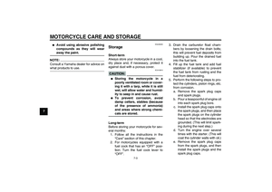
INSTRUMENT AND CONTROL FUNCTIONS
3-3
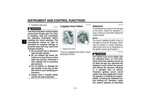
3 To unlock the steering
Push the key in, and then turn it to
ŌĆ£OFFŌĆØ while still pushing it.
WARNING
EWA10060
Never turn the key to ŌĆ£OFFŌĆØ or
ŌĆ£LOCKŌĆØ while the vehicle is moving,
otherwise the electrical systems will
be switched off, which may result in
loss of control or an accident. Make
sure that the vehicle is stopped be-
fore turning the key to ŌĆ£OFFŌĆØ orŌĆ£LOCKŌĆØ.
EAU10920
(Parking)
The steering is locked, the taillight and
auxiliary light are on, and the hazard
light can be turned on, but all other
electrical systems are off. The key can
be removed.
The steering must be locked before the
key can be turned to ŌĆ£ŌĆØ.
CAUTION:
ECA11020
Do not use the parking position for
an extended length of time, other-wise the battery may discharge.
EAU11002
Indicator and warning lights
EAU11020
Turn signal indicator light ŌĆ£ŌĆØ
This indicator light flashes when the
turn signal switch is pushed to the left or
right.
EAU11060
Neutral indicator light ŌĆ£ŌĆØ
This indicator light comes on when the
transmission is in the neutral position.
1. Push.
2. Turn.
1. Oil level warning light ŌĆ£ŌĆØ
2. Neutral indicator light ŌĆ£ŌĆØ
3. Turn signal indicator light ŌĆ£ŌĆØ
4. Engine trouble warning light ŌĆ£ŌĆØ
5. Immobilizer system indicator light ŌĆ£ŌĆØ
6. High beam indicator light ŌĆ£ŌĆØ
U5YSE0E0.book Page 3 Tuesday, June 8, 2004 2:04 PM
Page 18 of 82

INSTRUMENT AND CONTROL FUNCTIONS
3-4
3
EAU11080
High beam indicator light ŌĆ£ŌĆØ
This indicator light comes on when the
high beam of the headlight is switched
on.
EAU11120
Oil level warning light ŌĆ£ŌĆØ
This warning light comes on when the
engine oil level is low.
The electrical circuit of the warning light
can be checked by turning the key to
ŌĆ£ONŌĆØ.
If the warning light does not come on
for a few seconds, then go off, have a
Yamaha dealer check the electrical cir-
cuit.NOTE:Even if the oil level is sufficient, the
warning light may flicker when riding on
a slope or during sudden acceleration
or deceleration, but this is not a mal-function.
EAU11500
Engine trouble warning light ŌĆ£ŌĆØ
This warning light comes on or flashes
when an electrical circuit monitoring the
engine is defective. When this occurs,
have a Yamaha dealer check the self-
diagnosis system.
The electrical circuit of the warning light
can be checked by turning the key to
ŌĆ£ONŌĆØ. If the warning light does not come
on for a few seconds, then go off, have
a Yamaha dealer check the electrical
circuit.
EAU27020
Immobilizer system indicator light
ŌĆ£ŌĆØ
The electrical circuit of the indicator
light can be checked by turning the key
to ŌĆ£ONŌĆØ.
If the indicator light does not come on
for a few seconds, then go off, have a
Yamaha dealer check the electrical cir-
cuit.
When the key is turned to ŌĆ£OFFŌĆØ and 30
seconds have passed, the indicator
light will start flashing indicating the im-
mobilizer system is enabled. After 24hours have passed, the indicator light
will stop flashing, however the immobi-
lizer system is still enabled.
NOTE:This model is also equipped with a self-
diagnosis device for the immobilizer
system. If the immobilizer system is de-
fective, the indicator light will start flash-
ing a pattern when the key is turned to
ŌĆ£ONŌĆØ. When this occurs, have a
Yamaha dealer check the self-diagno-
sis system. However, if the indicator
light slowly flashes five times, and then
quickly flashes two times repeatedly,
this error could be caused by signal in-
terference. If this occurs, try the follow-ing.
1. Use the code re-registering key to
start the engine.NOTE:Make sure there are no other immobi-
lizer keys close to the main switch, and
do not keep more than one immobilizer
key on the same key ring! Immobilizer
system keys may cause signal interfer-
ence, which may prevent the enginefrom starting.
U5YSE0E0.book Page 4 Tuesday, June 8, 2004 2:04 PM
Page 19 of 82

INSTRUMENT AND CONTROL FUNCTIONS
3-5
3 2. If the engine starts, turn it off, and
try starting the engine with the
standard keys.
3. If one or both of the standard keys
do not start the engine, take the
vehicle, the code re-registering
key and both standard keys to a
Yamaha dealer and have the stan-
dard keys re-registered.
EAU11731
Speedometer unit The speedometer unit is equipped with
a digital odometer and a tripmeter. The
speedometer shows riding speed. The
odometer shows the total distance trav-
eled. The tripmeter shows the distance
traveled since it was last set to zero.
Pushing the ŌĆ£TRIPŌĆØ button switches the
display between the odometer mode
ŌĆ£ODOŌĆØ and the tripmeter mode ŌĆ£TRIPŌĆØ.
To reset the tripmeter, select it by push-
ing the ŌĆ£TRIPŌĆØ button, and then push
the ŌĆ£TRIPŌĆØ button again and hold it
down for at least one second. The trip-
meter can be used to estimate the dis-tance that can be traveled with a full
tank of fuel. This information will enable
you to plan future fuel stops.
NOTE:This model is not equipped with a ta-
chometer; however, it has a built-in
speed limiter, which prevents the en-
gine speed from exceeding approxi-
mately 6800 r/min and the vehicle
speed from exceeding approximately175 km/h (110 mi/h).
1.ŌĆ£TRIPŌĆØ button
2. Odometer/tripmeter
U5YSE0E0.book Page 5 Tuesday, June 8, 2004 2:04 PM
Page 20 of 82

INSTRUMENT AND CONTROL FUNCTIONS
3-6
3
EAU12343
Handlebar switches LeftRight
EAU12350
Pass switch ŌĆ£ŌĆØ
Press this switch to flash the headlight.
EAU12400
Dimmer switch ŌĆ£/ŌĆØ
Set this switch to ŌĆ£ŌĆØ for the high
beam and to ŌĆ£ŌĆØ for the low beam.
EAU12460
Turn signal switch ŌĆ£/ŌĆØ
To signal a right-hand turn, push this
switch to ŌĆ£ŌĆØ. To signal a left-hand
turn, push this switch to ŌĆ£ŌĆØ. When re-
leased, the switch returns to the centerposition. To cancel the turn signal
lights, push the switch in after it has re-
turned to the center position.
EAU12500
Horn switch ŌĆ£ŌĆØ
Press this switch to sound the horn.
EAU12660
Engine stop switch ŌĆ£/ŌĆØ
Set this switch to ŌĆ£ŌĆØ before starting
the engine. Set this switch to ŌĆ£ŌĆØ to
stop the engine in case of an emergen-
cy, such as when the vehicle overturns
or when the throttle cable is stuck.
EAU12710
Start switch ŌĆ£ŌĆØ
Push this switch to crank the engine
with the starter.CAUTION:
ECA10050
See page 5-1 for starting instruc-tions prior to starting the engine.
1. Pass switch ŌĆ£ŌĆØ
2. Dimmer switch ŌĆ£/ŌĆØ
3. Horn switch ŌĆ£ŌĆØ
4. Turn signal switch ŌĆ£/ŌĆØ
1. Engine stop switch ŌĆ£/ŌĆØ
2. Hazard switch ŌĆ£ŌĆØ
3. Start switch ŌĆ£ŌĆØ
U5YSE0E0.book Page 6 Tuesday, June 8, 2004 2:04 PM
Page 21 of 82

INSTRUMENT AND CONTROL FUNCTIONS
3-7
3
EAU12731
Hazard switch ŌĆ£ŌĆØ
With the key in the ŌĆ£ONŌĆØ or ŌĆ£ŌĆØ posi-
tion, use this switch to turn on the haz-
ard light (simultaneous flashing of all
turn signal lights).
The hazard light is used in case of an
emergency or to warn other drivers
when your vehicle is stopped where it
might be a traffic hazard.CAUTION:
ECA10060
Do not use the hazard light for an ex-
tended length of time, otherwise thebattery may discharge.
EAU12820
Clutch lever The clutch lever is located at the left
handlebar grip. To disengage the
clutch, pull the lever toward the handle-
bar grip. To engage the clutch, release
the lever. The lever should be pulled
rapidly and released slowly for smooth
clutch operation.
The clutch lever is equipped with a
clutch switch, which is part of the igni-
tion circuit cut-off system. (See page
3-17.)
EAU12880
Shift pedal The shift pedal is located on the left
side of the engine and is used in com-
bination with the clutch lever when
shifting the gears of the 5-speed con-
stant-mesh transmission equipped on
this motorcycle.NOTE:Use your toes or heel to shift up andyour toes to shift down.
1. Clutch lever
1. Shift pedal
U5YSE0E0.book Page 7 Tuesday, June 8, 2004 2:04 PM
Page 22 of 82
INSTRUMENT AND CONTROL FUNCTIONS
3-8
3
EAU12890
Brake lever The brake lever is located at the right
handlebar grip. To apply the front
brake, pull the lever toward the handle-
bar grip.
EAU12941
Brake pedal The brake pedal is on the right side of
the motorcycle. To apply the rear
brake, press down on the brake pedal.
EAU13120
Fuel tank cap To remove the fuel tank cap
Slide the lock cover open, insert the key
into the lock, and then turn it 1/4 turn
clockwise. The lock will be released
and the fuel tank cap can be removed.
To install the fuel tank cap
1. Insert the fuel tank cap into the
tank opening with the key inserted
in the lock and with the ŌĆ£ŌĆØ mark
facing forward.
1. Brake lever
1. Brake pedal
1. Fuel tank cap lock cover
2.ŌĆ£ŌĆØ mark
3. Unlock.
4. Lock.
U5YSE0E0.book Page 8 Tuesday, June 8, 2004 2:04 PM
Page 23 of 82

INSTRUMENT AND CONTROL FUNCTIONS
3-9
3 2. Turn the key counterclockwise to
the original position, remove it, and
then close the lock cover.
NOTE:The fuel tank cap cannot be installed
unless the key is in the lock. In addition,
the key cannot be removed if the cap isnot properly installed and locked.
WARNING
EWA10130
Make sure that the fuel tank cap isproperly installed before riding.
EAU13210
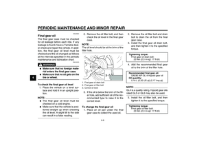
Fuel Make sure that there is sufficient fuel in
the tank. Fill the fuel tank to the bottom
of the filler tube as shown.
WARNING
EWA10880
�
Do not overfill the fuel tank, oth-
erwise it may overflow when the
fuel warms up and expands.
�
Avoid spilling fuel on the hot en-gine.
CAUTION:
ECA10070
Immediately wipe off spilled fuel
with a clean, dry, soft cloth, since
fuel may deteriorate painted surfac-es or plastic parts.
EAU13320
CAUTION:
ECA11400
Use only unleaded gasoline. The use
of leaded gasoline will cause severe
damage to internal engine parts,
such as the valves and piston rings,as well as to the exhaust system.
Your Yamaha engine has been de-
signed to use regular unleaded gaso-
line with a research octane number of
91 or higher. If knocking (or pinging) oc-
curs, use a gasoline of a different brand
1. Fuel tank filler tube
2. Fuel level
Recommended fuel:
REGULAR UNLEADED GASOLINE
ONLY
Fuel tank capacity:
17.0 L (4.49 US gal) (3.74 Imp.gal)
Fuel reserve amount:
4.5 L (1.19 US gal) (0.99 Imp.gal)
U5YSE0E0.book Page 9 Tuesday, June 8, 2004 2:04 PM
Page 24 of 82

INSTRUMENT AND CONTROL FUNCTIONS
3-10
3or premium unleaded fuel. Use of un-
leaded fuel will extend spark plug life
and reduce maintenance costs.
EAU13440
Catalytic converter This vehicle is equipped with a catalytic
converter in the muffler.
WARNING
EWA10860
The exhaust system is hot after op-
eration. Make sure that the exhaust
system has cooled down before do-ing any maintenance work.CAUTION:
ECA10700
The following precautions must be
observed to prevent a fire hazard or
other damages.�
Use only unleaded gasoline.
The use of leaded gasoline will
cause unrepairable damage to
the catalytic converter.
�
Never park the vehicle near pos-
sible fire hazards such as grass
or other materials that easily
burn.
�
Do not allow the engine to idletoo long.
EAU13550
Fuel cock The fuel cock supplies fuel from the
tank to the carburetors while also filter-
ing it.
The fuel cock lever positions are ex-
plained as follows and shown in the il-
lustrations.
OFF
With the fuel cock lever in this position,
fuel will not flow. Always turn the fuel
cock lever to this position when the en-
gine is not running.1. Pointed end positioned over ŌĆ£OFFŌĆØ
U5YSE0E0.book Page 10 Tuesday, June 8, 2004 2:04 PM