Page 25 of 88

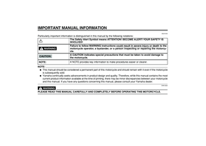
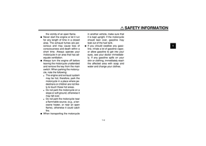
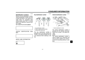
INSTRUMENT AND CONTROL FUNCTIONS
3-11
2
34
5
6
7
8
9
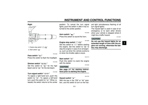
dial is aligned with the “” mark on the
brake lever.
EAU12941
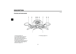
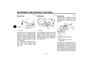
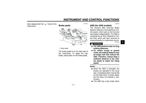
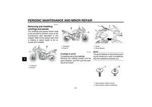
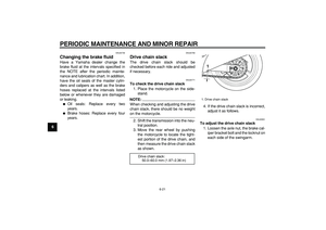
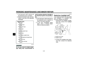
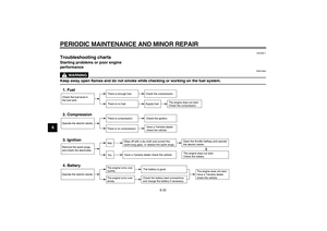
Brake pedal
The brake pedal is on the right side of
the motorcycle. To apply the rear
brake, press down on the brake pedal.
EAU26792
ABS (for ABS models)
The Yamaha ABS (Anti-lock Brake
System) features a dual electronic con-
trol system, which acts on the front and
rear brakes independently. The ABS is
monitored by an ECU (Electronic Con-
trol Unit), which will have recourse to
manual braking if a malfunction occurs.
WARNING
EWA10090
�
The ABS performs best on long
braking distances.
�
On certain (rough or gravel)
roads, the braking distance may
be longer with than without the
ABS. Therefore, always keep a
sufficient distance to the vehi-
cle ahead to match the riding
speed.
NOTE:
�
When the ABS is activated, the
brakes are operated in the usual
way. A pulsating action may be felt
at the brake lever or brake pedal,
but this does not indicate a mal-
function.
�
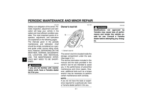
This ABS has a test mode which
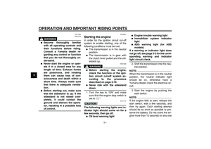
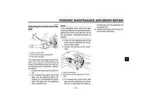
1. Brake pedal
1
Page 26 of 88
INSTRUMENT AND CONTROL FUNCTIONS
3-12
1
2
3
4
5
6
7
8
9
allows the owner to experience the
pulsating at the brake lever or
brake pedal when the ABS is oper-
ating. However, special tools are
required, so please consult your
Yamaha dealer when performing
this test.
EAU13090
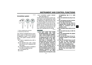
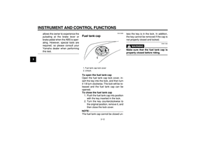
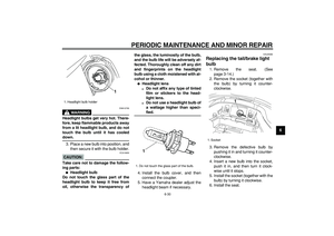
Fuel tank cap
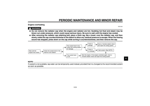
To open the fuel tank cap
Open the fuel tank cap lock cover, in-
sert the key into the lock, and then turn
it 1/8 turn clockwise. The lock will be re-
leased and the fuel tank cap can be
opened.
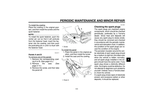
To close the fuel tank cap
1. Push the fuel tank cap into position
with the key inserted in the lock.
2. Turn the key counterclockwise to
the original position, remove it, and
then close the lock cover.
NOTE:
The fuel tank cap cannot be closed un-less the key is in the lock. In addition,
the key cannot be removed if the cap is
not properly closed and locked.
WARNING
EWA11090
Make sure that the fuel tank cap is
properly closed before riding.
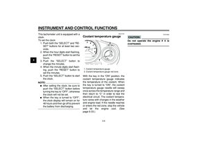
1. Fuel tank cap lock cover
2. Unlock.
1
2
Page 27 of 88

INSTRUMENT AND CONTROL FUNCTIONS
3-13
2
34
5
6
7
8
9
EAU13210
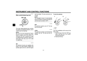
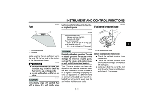
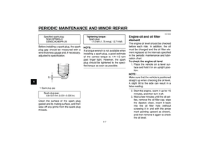
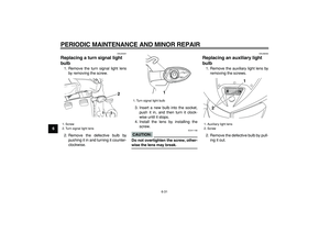
Fuel
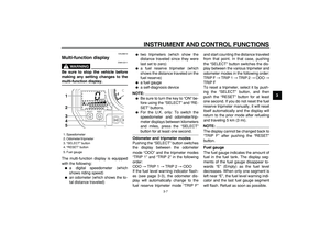
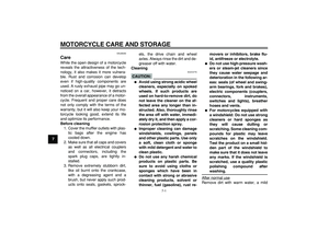
Make sure that there is sufficient fuel in
the tank. Fill the fuel tank to the bottom
of the filler tube as shown.
WARNING
EWA10880
�
Do not overfill the fuel tank, oth-
erwise it may overflow when the
fuel warms up and expands.
�
Avoid spilling fuel on the hot en-
gine.
CAUTION:
ECA10070
Immediately wipe off spilled fuel
with a clean, dry, soft cloth, sincefuel may deteriorate painted surfac-
es or plastic parts.
EAU13320
CAUTION:
ECA11400
Use only unleaded gasoline. The use
of leaded gasoline will cause severe
damage to internal engine parts,
such as the valves and piston rings,
as well as to the exhaust system.
Your Yamaha engine has been de-
signed to use regular unleaded gaso-
line with a research octane number of
91 or higher. If knocking (or pinging) oc-
curs, use a gasoline of a different brand
or premium unleaded fuel. Use of un-
leaded fuel will extend spark plug life
and reduce maintenance costs.
EAU13410
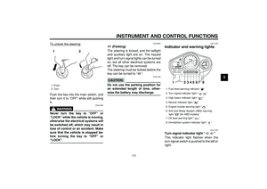
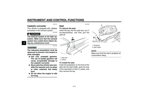
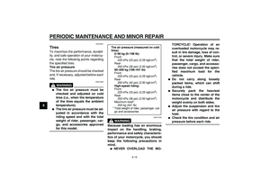
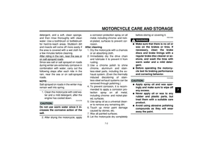
Fuel tank breather hose
Before operating the motorcycle:
�
Check the fuel tank breather hose
connection.
�
Check the fuel tank breather hose
for cracks or damage, and replace
it if damaged.
�
Make sure that the end of the fuel
tank breather hose is not blocked,
and clean it if necessary.
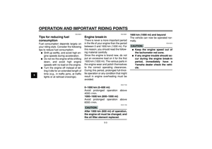
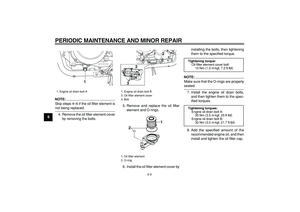
1. Fuel tank filler tube
2. Fuel level
1 2
Recommended fuel:
REGULAR UNLEADED
GASOLINE ONLY
Fuel tank capacity:
20.0 L (5.28 US gal) (4.40 Imp.gal)
Fuel reserve amount:
3.5 L (0.92 US gal) (0.77 Imp.gal)
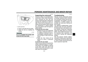
1. Fuel tank breather hose
1
Page 28 of 88

INSTRUMENT AND CONTROL FUNCTIONS
3-14
1
2
3
4
5
6
7
8
9
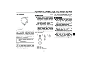
EAU13441
Catalytic converter
This vehicle is equipped with catalytic
converters in the exhaust system.
WARNING
EWA10860
The exhaust system is hot after op-
eration. Make sure that the exhaust
system has cooled down before do-
ing any maintenance work.
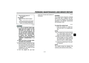
CAUTION:
ECA10700
The following precautions must be
observed to prevent a fire hazard or
other damages.
�
Use only unleaded gasoline.
The use of leaded gasoline will
cause unrepairable damage to
the catalytic converter.
�
Never park the vehicle near pos-
sible fire hazards such as grass
or other materials that easily
burn.
�
Do not allow the engine to idle
too long.
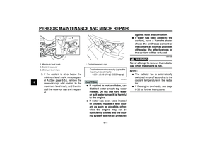
EAU13860
Seat
To remove the seat
Insert the key into the seat lock, turn it
counterclockwise, and then pull the
seat off.
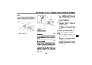
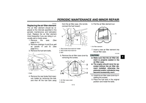
To install the seat
Insert the projections on the front of the
seat into the seat holder, push the rear
of the seat down to lock it in place, and
then remove the key.
NOTE:
Make sure that the seat is properly se-
cured before riding.
1. Seat lock
2. Unlock.1
2
1. Projection
2. Seat holder
1
2
Page 29 of 88

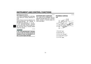
Wh")
INSTRUMENT AND CONTROL FUNCTIONS
3-15
2
34
5
6
7
8
9
EAU14411
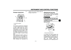
Storage compartment
This storage compartment is designed
to hold an optional genuine Yamaha
U-LOCK. (Other locks may not fit.)
When placing a U-LOCK in the storage
compartment, securely fasten it with
the straps. When the U-LOCK is not in
the storage compartment, be sure to
secure the straps to prevent losing
them.
When storing the owner’s manual or
other documents in the storage com-
partment, be sure to wrap them in a
plastic bag so that they will not get wet.
When washing the motorcycle, becareful not to let any water enter the
storage compartment.
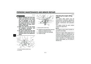
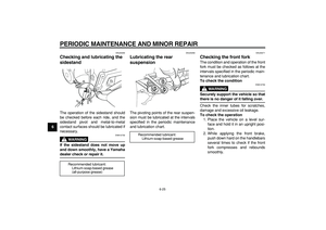
EAU14781
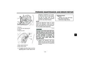
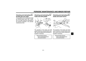
Adjusting the front fork
This front fork is equipped with spring
preload adjusting bolts and damping
force adjusting screws.
WARNING
EWA10180
Always adjust both fork legs equal-
ly, otherwise poor handling and loss
of stability may result.
Spring preload
To increase the spring preload and
thereby harden the suspension, turn
the adjusting bolt on each fork leg in di-
rection (a). To decrease the spring pre-
load and thereby soften the
suspension, turn the adjusting bolt on
1. U-LOCK bar (optional)
2. Strap
1
2
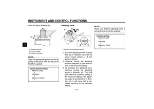
1. Spring preload adjusting bolt
1
(a)(b)
Page 30 of 88
.
NOTE:
Align the appropriate groove on the ad-
justing mechanism with the top of the
front fork cap bolt.")
INSTRUMENT AND CONTROL FUNCTIONS
3-16
1
2
3
4
5
6
7
8
9
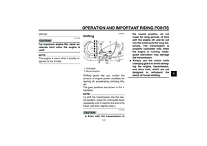
each fork leg in direction (b).
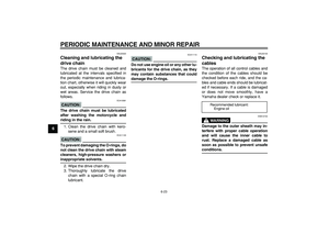
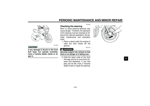
NOTE:
Align the appropriate groove on the ad-
justing mechanism with the top of the
front fork cap bolt.
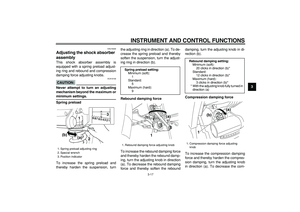
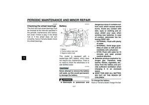
Damping force
1. Turn the adjusting screw on each
fork leg in direction (a) until the
screw moves almost a 1/2 turn
without clicking.
2. Continue turning the adjusting
screw in direction (a) until it clicks.
This is the minimum setting.
3. To increase the damping force,
continue turning the adjusting
screw in direction (a). The third
click after the minimum setting is
the maximum setting. If the adjust-
ing screw is turned further in direc-
tion (a), it will move half a turn
before returning to the minimum
setting.
NOTE:
Make sure that the adjusting screw is
turned to one of the four settings.
1. Standard setting
2. Current setting
3. Front fork cap bolt
Spring preload setting:
Minimum (soft):
8
Standard:
7
Maximum (hard):
1
2
31
7654321
8
1. Damping force adjusting screw(a) 1
1
2
3 4
Damping setting:
Minimum (soft):
1
Standard:
2
Maximum (hard):
4
Page 31 of 88

INSTRUMENT AND CONTROL FUNCTIONS
3-17
2
34
5
6
7
8
9
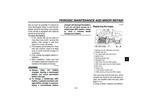
EAU15030
Adjusting the shock absorber
assembly
This shock absorber assembly is
equipped with a spring preload adjust-
ing ring and rebound and compression
damping force adjusting knobs.
CAUTION:
ECA10100
Never attempt to turn an adjusting
mechanism beyond the maximum or
minimum settings.
Spring preload
To increase the spring preload and
thereby harden the suspension, turnthe adjusting ring in direction (a). To de-
crease the spring preload and thereby
soften the suspension, turn the adjust-
ing ring in direction (b).
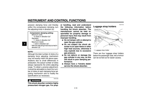
Rebound damping force
To increase the rebound damping force
and thereby harden the rebound damp-
ing, turn the adjusting knob in direction
(a). To decrease the rebound damping
force and thereby soften the rebounddamping, turn the adjusting knob in di-
rection (b).
Compression damping force
To increase the compression damping
force and thereby harden the compres-
sion damping, turn the adjusting knob
in direction (a). To decrease the com-
1. Spring preload adjusting ring
2. Special wrench
3. Position indicator
(a) (b)3
1
2
1 2 3 4 5 6 7 8 9
Spring preload setting:
Minimum (soft):
1
Standard:
5
Maximum (hard):
9
1. Rebound damping force adjusting knob1
(a)
(b)
Rebound damping setting:
Minimum (soft):
20 clicks in direction (b)*
Standard:
12 clicks in direction (b)*
Maximum (hard):
3 clicks in direction (b)*
* With the adjusting knob fully turned in
direction (a)
1. Compression damping force adjusting
knob
1
(a)
(b)
Page 32 of 88
.
NOTE:
Although the total num")
INSTRUMENT AND CONTROL FUNCTIONS
3-18
1
2
3
4
5
6
7
8
9
pression damping force and thereby
soften the compression damping, turn
the adjusting knob in direction (b).
NOTE:
Although the total number of clicks of a
damping force adjusting mechanism
may not exactly match the above spec-
ifications due to small differences in
production, the actual number of clicks
always represents the entire adjusting
range. To obtain a precise adjustment,
it would be advisable to check the num-
ber of clicks of each damping force ad-
justing mechanism and to modify the
specifications as necessary.
WARNING
EWA10220
This shock absorber contains highly
pressurized nitrogen gas. For prop-er handling, read and understand
the following information before
handling the shock absorber. The
manufacturer cannot be held re-
sponsible for property damage or
personal injury that may result from
improper handling.
�
Do not tamper with or attempt to
open the gas cylinder.
�
Do not subject the shock ab-
sorber to an open flame or other
high heat sources, otherwise it
may explode due to excessive
gas pressure.
�
Do not deform or damage the
gas cylinder in any way, as this
will result in poor damping per-
formance.
�
Always have a Yamaha dealer
service the shock absorber.
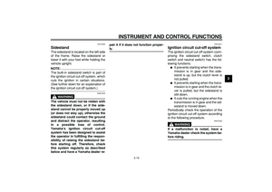
EAU15140
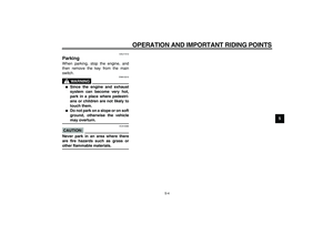
Luggage strap holders
There are four luggage strap holders
below the passenger seat, two of which
can be turned out for easier access.
Compression damping setting:
Minimum (soft):
12 clicks in direction (b)*
Standard:
11 clicks in direction (b)*
Maximum (hard):
1 click in direction (b)*
* With the adjusting knob fully turned in
direction (a)
1. Luggage strap holder
1(×4)