Page 17 of 88

INSTRUMENT AND CONTROL FUNCTIONS
3-3
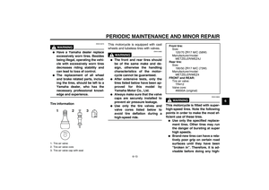
3 To unlock the steering
Push the key in, and then turn it to
ŌĆ£OFFŌĆØ while still pushing it.
WARNING
EWA10060
Never turn the key to ŌĆ£OFFŌĆØ or
ŌĆ£LOCKŌĆØ while the vehicle is moving,
otherwise the electrical systems will
be switched off, which may result in
loss of control or an accident. Make
sure that the vehicle is stopped be-
fore turning the key to ŌĆ£OFFŌĆØ orŌĆ£LOCKŌĆØ.
EAU10940
(Parking)
The steering is locked, and the taillight,
license plate light and auxiliary lights
are on. The hazard light and turn signal
lights can be turned on, but all other
electrical systems are off. The key can
be removed.
The steering must be locked before the
key can be turned to ŌĆ£ŌĆØ.
CAUTION:
ECA11020
Do not use the parking position for
an extended length of time, other-wise the battery may discharge.
EAU11002
Indicator and warning lights
EAU11030
Turn signal indicator lights ŌĆ£ŌĆØ and
ŌĆ£ŌĆØ
The corresponding indicator light flash-
es when the turn signal switch is
pushed to the left or right.
EAU11060
Neutral indicator light ŌĆ£ŌĆØ
This indicator light comes on when the
transmission is in the neutral position.
1. Push.
2. Turn.
1. Engine trouble warning light ŌĆ£ŌĆØ
2. Left turn signal indicator light ŌĆ£ŌĆØ
3. Neutral indicator light ŌĆ£ŌĆØ
4. Immobilizer system indicator light
5. Fuel level warning light ŌĆ£ŌĆØ
6. Right turn signal indicator light ŌĆ£ŌĆØ
7. High beam indicator light ŌĆ£ŌĆØ
U5YUE0E0.book Page 3 Monday, November 15, 2004 8:48 AM
Page 18 of 88

INSTRUMENT AND CONTROL FUNCTIONS
3-4
3
EAU11080
High beam indicator light ŌĆ£ŌĆØ
This indicator light comes on when the
high beam of the headlight is switched
on.
EAU11361
Fuel level warning light ŌĆ£ŌĆØ
This warning light comes on when the
fuel level drops below approximately
3.0 L (0.79 US gal) (0.66 Imp.gal).
When this occurs, refuel as soon as
possible.
The electrical circuit of the warning light
can be checked by turning the key to
ŌĆ£ONŌĆØ.
If the warning light does not come on
for a few seconds, and then go off,
have a Yamaha dealer check the elec-
trical circuit.NOTE:This model is also equipped with a self-
diagnosis device for the fuel level de-
tection circuit. If the fuel level detection
circuit is defective, the following cycle
will be repeated until the malfunction is
corrected: The fuel level warning lightwill flash eight times, and then go off for
3.0 seconds. If this occurs, have a
Yamaha dealer check the vehicle.
EAU11530
Engine trouble warning light ŌĆ£ŌĆØ
This warning light comes on or flashes
when an electrical circuit monitoring the
engine is defective. When this occurs,
have a Yamaha dealer check the self-
diagnosis system. (See page 3-5 for an
explanation of the self-diagnosis de-
vice.)
The electrical circuit of the warning light
can be checked by turning the key to
ŌĆ£ONŌĆØ. If the warning light does not come
on for a few seconds, then go off, have
a Yamaha dealer check the electrical
circuit.
EAU26873
Immobilizer system indicator light
ŌĆ£ŌĆØ
The electrical circuit of the indicator
light can be checked by turning the key
to ŌĆ£ONŌĆØ.If the indicator light does not come on
for a few seconds, then go off, have a
Yamaha dealer check the electrical cir-
cuit.
When the key is turned to ŌĆ£OFFŌĆØ and 30
seconds have passed, the indicator
light will start flashing indicating the im-
mobilizer system is enabled. After 24
hours have passed, the indicator light
will stop flashing, however the immobi-
lizer system is still enabled.
This model is also equipped with a self-
diagnosis device for the immobilizer
system. (See page 3-5 for an explana-
tion of the self-diagnosis device.)
U5YUE0E0.book Page 4 Monday, November 15, 2004 8:48 AM
Page 19 of 88

INSTRUMENT AND CONTROL FUNCTIONS
3-5
3
EAU36852
Multi-function display
WARNING
EWA12421
Be sure to stop the vehicle before
making any setting changes to themulti-function meter unit.
The multi-function display is equipped
with the following:�
a speedometer (which shows the
riding speed)
�
a tachometer (which shows engine
speed)
�
an odometer (which shows the to-
tal distance traveled)
�
two tripmeters (which show the
distance traveled since they were
last set to zero)
�
a fuel reserve tripmeter (which
shows the distance traveled since
the fuel level warning light came
on)
�
a clock
�
a self-diagnosis device
�
a brightness control mode
NOTE:�
Be sure to turn the key to ŌĆ£ONŌĆØ be-
fore using the ŌĆ£SELECTŌĆØ and ŌĆ£RE-
SETŌĆØ buttons except for setting the
brightness control mode.
�
For the U.K. only: To switch the
speedometer and odometer/trip-
meter displays between kilometers
and miles, press the ŌĆ£SELECTŌĆØbutton for at least two seconds.Tachometer
The electric tachometer allows the rider
to monitor the engine speed and keep it
within the ideal power range.
When the key is turned to ŌĆ£ONŌĆØ, the ta-
chometer needle will sweep once
across the r/min range and then return
to zero r/min in order to test the electri-
cal circuit.
CAUTION:
ECA10031
Do not operate the engine in the ta-
chometer red zone.Red zone: 5500 r/min and above
The tachometer needle flashes when it
reaches and exceeds the red zone.
1. Clock
2.ŌĆ£RESETŌĆØ button
3. Tachometer
4.ŌĆ£SELECTŌĆØ button
5. Speedometer
6. Odometer/tripmeter/fuel reserve tripmeter
1. Tachometer
2. Tachometer red zone
U5YUE0E0.book Page 5 Monday, November 15, 2004 8:48 AM
Page 20 of 88

INSTRUMENT AND CONTROL FUNCTIONS
3-6
3Clock mode
To set the clock
1. Push the ŌĆ£SELECTŌĆØ button and
ŌĆ£RESETŌĆØ button together for at
least two seconds.
2. When the hour digits start flashing,
push the ŌĆ£RESETŌĆØ button to set the
hours.
3. Push the ŌĆ£SELECTŌĆØ button, and
the minute digits will start flashing.
4. Push the ŌĆ£RESETŌĆØ button to set
the minutes.
5. Push the ŌĆ£SELECTŌĆØ button and
then release it to start the clock.Odometer and tripmeter modes
Pushing the ŌĆ£SELECTŌĆØ button switches
the display between the odometer
mode ŌĆ£ODOŌĆØ and the tripmeter modes
ŌĆ£TRIP 1ŌĆØ and ŌĆ£TRIP 2ŌĆØ in the following
order:
ODO ŌåÆ TRIP 1 ŌåÆ TRIP 2 ŌåÆ ODO
If the fuel level warning light comes on
(see page 3-3), the odometer display
will automatically change to the fuel re-
serve tripmeter mode ŌĆ£F-TRIPŌĆØ and
start counting the distance traveled
from that point. In that case, pushing
the ŌĆ£SELECTŌĆØ button switches the dis-
play between the various tripmeter and
odometer modes in the following order:
F-TRIP ŌåÆ TRIP 1 ŌåÆ TRIP 2 ŌåÆ ODO ŌåÆ
F-TRIPTo reset a tripmeter, select it by push-
ing the ŌĆ£SELECTŌĆØ button, and then
push the ŌĆ£RESETŌĆØ button for at least
one second. If you do not reset the fuel
reserve tripmeter manually, it will reset
itself automatically and the display will
return to the prior mode after refueling
and traveling 5 km (3 mi).
Self-diagnosis devices
This model is equipped with a self-diag-
nosis device for various electrical cir-
cuits.
If any of those circuits are defective, the
engine trouble warning light will come
on, and then the odometer/tripmeter
display will indicate a two-digit error
code (e.g., 12, 13, 14).
This model is also equipped with a self-
diagnosis device for the immobilizer
system.
If any of the immobilizer system circuits
are defective, the immobilizer system
indicator light will flash, and then the
display will indicate a two-digit error
code (e.g., 51, 52, 53).1. Clock
1. Odometer/tripmeter/fuel reserve tripmeter
U5YUE0E0.book Page 6 Monday, November 15, 2004 8:48 AM
Page 21 of 88

INSTRUMENT AND CONTROL FUNCTIONS
3-7
3
NOTE:If the display indicates error code 52,
this could be caused by transponder in-
terference. If this error code appears,try the following.
1. Use the code re-registering key to
start the engine.NOTE:Make sure there are no other immobi-
lizer keys close to the main switch, and
do not keep more than one immobilizer
key on the same key ring! Immobilizer
system keys may cause signal interfer-
ence, which may prevent the enginefrom starting.
2. If the engine starts, turn it off and
try starting the engine with the
standard keys.
3. If one or both of the standard keys
do not start the engine, take the
vehicle, the code re-registering
key and both standard keys to a
Yamaha dealer and have the stan-
dard keys re-registered.
If the display indicates any error codes,
note the code number, and then have a
Yamaha dealer check the vehicle.
CAUTION:
ECA11590
If the display indicates an error
code, the vehicle should be checked
as soon as possible in order to avoidengine damage.
Brightness control mode
The brightness can be adjusted for the
following:�
the tachometer panel (item num-
ber ŌĆ£1ŌĆØ)
�
the LCD (item number ŌĆ£2ŌĆØ)
�
the tachometer needle (item num-
ber ŌĆ£3ŌĆØ)Select the brightness control mode as
follows.
1. Turn the key to ŌĆ£OFFŌĆØ.
2. Push and hold the ŌĆ£SELECTŌĆØ but-
ton.
3. Turn the key to ŌĆ£ONŌĆØ, and then re-
lease the ŌĆ£SELECTŌĆØ button after
five seconds.
Item number ŌĆ£1ŌĆØ is displayed.
4. Adjust the tachometer panel
brightness level by pushing the
ŌĆ£RESETŌĆØ button.
5. Push the ŌĆ£SELECTŌĆØ button to se-
lect the LCD.
Item number ŌĆ£2ŌĆØ is displayed.
1. Tachometer panel
2. LCD
3. Tachometer needle
1. Tachometer panel
2. Item number
3. Brightness level
U5YUE0E0.book Page 7 Monday, November 15, 2004 8:48 AM
Page 22 of 88
INSTRUMENT AND CONTROL FUNCTIONS
3-8
3Adjust the LCD brightness level by
pushing the ŌĆ£RESETŌĆØ button.
6. Push the ŌĆ£SELECTŌĆØ button to se-
lect the tachometer needle.
Item number ŌĆ£3ŌĆØ is displayed.
Adjust the tachometer needle
brightness level by pushing the
ŌĆ£RESETŌĆØ button.7. Push the ŌĆ£SELECTŌĆØ button and the
multi-function display will return to
the odometer or tripmeter mode.
EAU12331
Anti-theft alarm (optional) This model can be equipped with an
optional anti-theft alarm by a Yamaha
dealer. Contact a Yamaha dealer for
more information.
1. LCD
2. Item number
3. Brightness level
1. Tachometer needle
2. Item number
3. Brightness level
U5YUE0E0.book Page 8 Monday, November 15, 2004 8:48 AM
Page 23 of 88

INSTRUMENT AND CONTROL FUNCTIONS
3-9
3
EAU12343
Handlebar switches LeftRight
EAU12350
Pass switch ŌĆ£ŌĆØ
Press this switch to flash the headlight.
EAU12400
Dimmer switch ŌĆ£/ŌĆØ
Set this switch to ŌĆ£ŌĆØ for the high
beam and to ŌĆ£ŌĆØ for the low beam.
EAU12460
Turn signal switch ŌĆ£/ŌĆØ
To signal a right-hand turn, push this
switch to ŌĆ£ŌĆØ. To signal a left-hand
turn, push this switch to ŌĆ£ŌĆØ. When re-
leased, the switch returns to the centerposition. To cancel the turn signal
lights, push the switch in after it has re-
turned to the center position.
EAU12500
Horn switch ŌĆ£ŌĆØ
Press this switch to sound the horn.
EAU12660
Engine stop switch ŌĆ£/ŌĆØ
Set this switch to ŌĆ£ŌĆØ before starting
the engine. Set this switch to ŌĆ£ŌĆØ to
stop the engine in case of an emergen-
cy, such as when the vehicle overturns
or when the throttle cable is stuck.
EAU12710
Start switch ŌĆ£ŌĆØ
Push this switch to crank the engine
with the starter.CAUTION:
ECA10050
See page 5-1 for starting instruc-tions prior to starting the engine.
1. Pass switch ŌĆ£ŌĆØ
2. Dimmer switch ŌĆ£/ŌĆØ
3. Turn signal switch ŌĆ£/ŌĆØ
4. Horn switch ŌĆ£ŌĆØ
5. Hazard switch ŌĆ£ŌĆØ
1. Engine stop switch ŌĆ£/ŌĆØ
2. Start switch ŌĆ£ŌĆØ
U5YUE0E0.book Page 9 Monday, November 15, 2004 8:48 AM
Page 24 of 88

INSTRUMENT AND CONTROL FUNCTIONS
3-10
3
EAU12732
Hazard switch ŌĆ£ŌĆØ
With the key in the ŌĆ£ONŌĆØ or ŌĆ£ŌĆØ posi-
tion, use this switch to turn on the haz-
ard light (simultaneous flashing of all
turn signal lights).
The hazard light is used in case of an
emergency or to warn other drivers
when your vehicle is stopped where it
might be a traffic hazard.CAUTION:
ECA10061
Do not use the hazard lights for an
extended length of time with the en-
gine not running, otherwise the bat-tery may discharge.
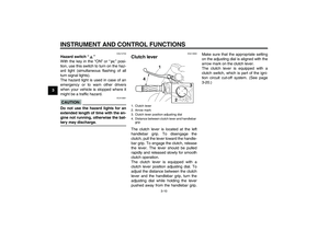
EAU12830
Clutch lever The clutch lever is located at the left
handlebar grip. To disengage the
clutch, pull the lever toward the handle-
bar grip. To engage the clutch, release
the lever. The lever should be pulled
rapidly and released slowly for smooth
clutch operation.
The clutch lever is equipped with a
clutch lever position adjusting dial. To
adjust the distance between the clutch
lever and the handlebar grip, turn the
adjusting dial while holding the lever
pushed away from the handlebar grip.Make sure that the appropriate setting
on the adjusting dial is aligned with the
arrow mark on the clutch lever.
The clutch lever is equipped with a
clutch switch, which is part of the igni-
tion circuit cut-off system. (See page
3-20.)1. Clutch lever
2. Arrow mark
3. Clutch lever position adjusting dial
4. Distance between clutch lever and handlebar
grip
U5YUE0E0.book Page 10 Monday, November 15, 2004 8:48 AM