Page 25 of 88
INSTRUMENT AND CONTROL FUNCTIONS
3-11
3
EAU12870
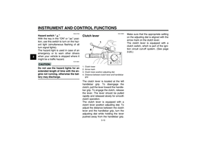
Shift pedal The shift pedal is located on the left
side of the engine and is used in com-
bination with the clutch lever when
shifting the gears of the 5-speed con-
stant-mesh transmission equipped on
this motorcycle.
EAU33850
Brake lever The brake lever is located at the right
handlebar grip. To apply the front
brake, pull the lever toward the handle-
bar grip.
The brake lever is equipped with a po-
sition adjusting knob. To adjust the dis-
tance between the brake lever and the
handlebar grip, turn the adjusting knob
while holding the lever pushed away
from the handlebar grip. When the de-
sired position is obtained, be sure to setit by aligning a groove on the adjusting
knob with the “” mark on the brake
lever.
1. Shift pedal
1. Brake lever
2. Brake lever position adjusting knob
3. Distance between brake lever and handlebar
grip
4.“” mark
U5YUE0E0.book Page 11 Monday, November 15, 2004 8:48 AM
Page 26 of 88
INSTRUMENT AND CONTROL FUNCTIONS
3-12
3
EAU12941
Brake pedal The brake pedal is on the right side of
the motorcycle. To apply the rear
brake, press down on the brake pedal.
EAU13070
Fuel tank cap To open the fuel tank cap
Open the fuel tank cap lock cover, in-
sert the key into the lock, and then turn
it 1/4 turn clockwise. The lock will be re-
leased and the fuel tank cap can be
opened.
To close the fuel tank cap
1. Push the fuel tank cap into position
with the key inserted in the lock.
2. Turn the key counterclockwise to
the original position, remove it, and
then close the lock cover.
NOTE:The fuel tank cap cannot be closed un-
less the key is in the lock. In addition,
the key cannot be removed if the cap isnot properly closed and locked.
WARNING
EWA11090
Make sure that the fuel tank cap isproperly closed before riding.
1. Brake pedal
1. Fuel tank cap lock cover
2. Unlock.
U5YUE0E0.book Page 12 Monday, November 15, 2004 8:48 AM
Page 27 of 88

INSTRUMENT AND CONTROL FUNCTIONS
3-13
3
EAU13210
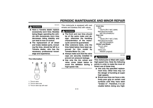
Fuel Make sure that there is sufficient fuel in
the tank. Fill the fuel tank to the bottom
of the filler tube as shown.
WARNING
EWA10880
�
Do not overfill the fuel tank, oth-
erwise it may overflow when the
fuel warms up and expands.
�
Avoid spilling fuel on the hot en-gine.
CAUTION:
ECA10070
Immediately wipe off spilled fuel
with a clean, dry, soft cloth, since
fuel may deteriorate painted surfac-es or plastic parts.
EAU33500
CAUTION:
ECA11400
Use only unleaded gasoline. The use
of leaded gasoline will cause severe
damage to internal engine parts,
such as the valves and piston rings,as well as to the exhaust system.
Your Yamaha engine has been de-
signed to use regular unleaded gaso-
line with a research octane number of
91 or higher. If knocking (or pinging) oc-curs, use a gasoline of a different brand
or premium unleaded fuel. Use of un-
leaded fuel will extend spark plug life
and reduce maintenance costs.
1. Fuel tank filler tube
2. Fuel level
Recommended fuel:
REGULAR UNLEADED GASOLINE
ONLY
Fuel tank capacity:
15.0 L (3.96 US gal) (3.30 Imp.gal)
Fuel reserve amount (when the fuel
level warning symbol comes on):
3.0 L (0.79 US gal) (0.66 Imp.gal)
U5YUE0E0.book Page 13 Monday, November 15, 2004 8:48 AM
Page 28 of 88

INSTRUMENT AND CONTROL FUNCTIONS
3-14
3
EAU34071
Fuel tank breather/overflow
hose Before operating the motorcycle:�
Check the fuel tank breather/over-
flow hose connection.
�
Check the fuel tank breather/over-
flow hose for cracks or damage,
and replace it if damaged.
�
Make sure that the end of the fuel
tank breather/overflow hose is not
blocked, and clean it if necessary.
�
Make sure that the end of the fuel
tank breather/overflow hose is po-
sitioned outside of the cowling.
EAU13441
Catalytic converter This vehicle is equipped with catalytic
converters in the exhaust system.
WARNING
EWA10860
The exhaust system is hot after op-
eration. Make sure that the exhaust
system has cooled down before do-ing any maintenance work.CAUTION:
ECA10700
The following precautions must be
observed to prevent a fire hazard or
other damages.�
Use only unleaded gasoline.
The use of leaded gasoline will
cause unrepairable damage to
the catalytic converter.
�
Never park the vehicle near pos-
sible fire hazards such as grass
or other materials that easily
burn.
�
Do not allow the engine to idletoo long.
EAU36691
Seat To remove the seat
1. Insert the key into the seat lock,
and then turn it clockwise.
2. Pull the seat off.
To install the seat
1. Insert the projections into the hold-
ers as shown.
1. Fuel tank breather/overflow hose
2. Cowling
1. Seat lock
2. Unlock.
U5YUE0E0.book Page 14 Monday, November 15, 2004 8:48 AM
Page 29 of 88

INSTRUMENT AND CONTROL FUNCTIONS
3-15
3
2. Push the center of the seat down
to lock it in place.
3. Remove the key.
NOTE:Make sure that the seat is properly se-cured before riding.
EAU36930
Adjusting the front fork This front fork is equipped with spring
preload adjusting bolts, rebound damp-
ing force adjusting screws and com-
pression damping force adjusting
screws.
WARNING
EWA10180
Always adjust both fork legs equal-
ly, otherwise poor handling and lossof stability may result.
Spring preload
To increase the spring preload and
thereby harden the suspension, turn
the adjusting bolt on each fork leg in di-
rection (a). To decrease the spring pre-load and thereby soften the
suspension, turn the adjusting bolt on
each fork leg in direction (b).
NOTE:Align the appropriate groove on the ad-
justing mechanism with the top of thefront fork collar.
1. Seat holder
2. Projection
1. Spring preload adjusting bolt
1. Current setting
2. Front fork collar
Spring preload setting:
Minimum (soft):
0
Standard:
2
Maximum (hard):
5
U5YUE0E0.book Page 15 Monday, November 15, 2004 8:48 AM
Page 30 of 88
.")
INSTRUMENT AND CONTROL FUNCTIONS
3-16
3Rebound damping force
To increase the rebound damping force
and thereby harden the rebound damp-
ing, turn the adjusting screw on each
fork leg in direction (a). To decrease the
rebound damping force and thereby
soften the rebound damping, turn the
adjusting screw on each fork leg in di-
rection (b).Compression damping force
To increase the compression damping
force and thereby harden the compres-
sion damping, turn the adjusting screw
on each fork leg in direction (a). To de-
crease the compression damping force
and thereby soften the compression
damping, turn the adjusting screw on
each fork leg in direction (b).
CAUTION:
ECA10100
Never attempt to turn an adjusting
mechanism beyond the maximum orminimum settings.NOTE:Although the total number of clicks of a
damping force adjusting mechanism
may not exactly match the above spec-
ifications due to small differences in
production, the actual number of clicks
always represents the entire adjusting
range. To obtain a precise adjustment,
it would be advisable to check the num-
ber of clicks of each damping force ad-
justing mechanism and to modify thespecifications as necessary.
1. Rebound damping force adjusting screwRebound damping setting:
Minimum (soft):
17 click(s) in direction (b)*
Standard:
15 click(s) in direction (b)*
Maximum (hard):
1 click(s) in direction (b)*
* With the adjusting screw fully turned
in direction (a)
1. Compression damping force adjusting screwCompression damping setting:
Minimum (soft):
16 click(s) in direction (b)*
Standard:
7 click(s) in direction (b)*
Maximum (hard):
1 click(s) in direction (b)*
* With the adjusting screw fully turned
in direction (a)
U5YUE0E0.book Page 16 Monday, November 15, 2004 8:48 AM
Page 31 of 88

INSTRUMENT AND CONTROL FUNCTIONS
3-17
3
EAU36751
Adjusting the shock absorber
assembly This shock absorber assembly is
equipped with a spring preload adjust-
ing nut, a rebound damping force ad-
justing knob and a compression
damping force adjusting screw.CAUTION:
ECA10100
Never attempt to turn an adjusting
mechanism beyond the maximum orminimum settings.
Spring preload
Adjust the spring preload as follows.
1. Loosen the locknut.2. To increase the spring preload and
thereby harden the suspension,
turn the adjusting nut in direction
(a). To decrease the spring pre-
load and thereby soften the sus-
pension, turn the adjusting nut in
direction (b).
NOTE:The spring preload setting is deter-
mined by measuring distance A, shown
in the illustration. The longer distance A
is, the lower the spring preload; the
shorter distance A is, the higher thespring preload.3. Tighten the locknut to the specified
torque.
1. Locknut
2. Spring preload adjusting nut
1. Special wrench
1. Distance A
Spring preload:
Minimum (soft):
Distance A = 155.0 mm (6.10 in)
Standard:
Distance A = 150.0 mm (5.91 in)
Maximum (hard):
Distance A = 145.0 mm (5.71 in)
Tightening torque:
Locknut:
42 Nm (4.2 m·kgf, 30 ft·lbf)
U5YUE0E0.book Page 17 Monday, November 15, 2004 8:48 AM
Page 32 of 88

INSTRUMENT AND CONTROL FUNCTIONS
3-18
3
CAUTION:
ECA10120
Always tighten the locknut against
the adjusting nut, and then tightenthe locknut to the specified torque.
Rebound damping force
To increase the rebound damping force
and thereby harden the rebound damp-
ing, turn the adjusting knob in direction
(a). To decrease the rebound damping
force and thereby soften the rebound
damping, turn the adjusting knob in di-
rection (b).Compression damping force
To increase the compression damping
force and thereby harden the compres-
sion damping, turn the adjusting screw
in direction (a). To decrease the com-
pression damping force and thereby
soften the compression damping, turn
the adjusting screw in direction (b).
NOTE:
Although the total number of clicks of a
damping force adjusting mechanism
may not exactly match the above spec-
ifications due to small differences in
production, the actual number of clicks
always represents the entire adjusting
range. To obtain a precise adjustment,
it would be advisable to check the num-
ber of clicks of each damping force ad-
justing mechanism and to modify thespecifications as necessary.
WARNING
EWA10220
This shock absorber contains highly
pressurized nitrogen gas. For prop-
er handling, read and understand
the following information before
handling the shock absorber. The
1. Rebound damping force adjusting knob
Rebound damping setting:
Minimum (soft):
20 click(s) in direction (b)*
Standard:
12 click(s) in direction (b)*
Maximum (hard):
3 click(s) in direction (b)*
* With the adjusting knob fully turned
in direction (a)1. Compression damping force adjusting screw
Compression damping setting:
Minimum (soft):
12 click(s) in direction (b)*
Standard:
10 click(s) in direction (b)*
Maximum (hard):
1 click(s) in direction (b)*
* With the adjusting screw fully turned
in direction (a)
U5YUE0E0.book Page 18 Monday, November 15, 2004 8:48 AM