Page 65 of 88
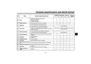
PERIODIC MAINTENANCE AND MINOR REPAIR
6-27
6 charger will damage the battery.
If you do not have access to a
sealed-type (MF) battery charg-
er, have a Yamaha dealer
charge your battery.
EAU32842
Replacing the fuses The main fuse is located under the fuel
tank. (See page 6-11.)
The fuse box is located behind panel A.
(See page 6-5.)
If a fuse is blown, replace it as follows.
1. Turn the key to “OFF” and turn off
the electrical circuit in question.
2. Remove the blown fuse, and then
install a new fuse of the specified
amperage.1. Main fuse
2. Spare fuse
1. Fuse box
1. Headlight fuse
2. Signaling system fuse
3. Ignition fuse
4. Radiator fan fuse
5. Backup fuse (for odometer, clock and immo-
bilizer system)
6. Electronic fuel injection fuse
7. Spare fuse
8. Parking lighting fuse
U1B3E1E0.book Page 27 Thursday, July 8, 2004 11:49 AM
Page 66 of 88

PERIODIC MAINTENANCE AND MINOR REPAIR
6-28
6
CAUTION:
ECA10640
Do not use a fuse of a higher amper-
age rating than recommended to
avoid causing extensive damage to
the electrical system and possibly afire.
3. Turn the key to “ON” and turn on
the electrical circuit in question to
check if the device operates.
4. If the fuse immediately blows
again, have a Yamaha dealer
check the electrical system.
EAU34380
Replacing the headlight bulb This model is equipped with a quartz
bulb headlight. If the headlight bulb
burns out, replace it as follows.
1. Remove the headlight unit by re-
moving the bolts on each side.
2. Disconnect the headlight coupler,
and then remove the bulb cover.3. Unhook the headlight bulb holder,
and then remove the defective
bulb.
Specified fuses:
Main fuse:
30.0 A
Headlight fuse:
20.0 A
Signaling system fuse:
10.0 A
Ignition fuse:
10.0 A
Radiator fan fuse:
20.0 A
Electronic fuel injection fuse:
10.0 A
Backup fuse:
10.0 A
Parking lighting fuse:
10.0 A
1. Bolt
1. Headlight bulb cover
2. Headlight coupler
1. Headlight bulb holder
2. Headlight bulb
U1B3E1E0.book Page 28 Thursday, July 8, 2004 11:49 AM
Page 67 of 88

PERIODIC MAINTENANCE AND MINOR REPAIR
6-29
6
WARNING
EWA10790
Headlight bulbs get very hot. There-
fore, keep flammable products away
from a lit headlight bulb, and do not
touch the bulb until it has cooleddown.
4. Place a new headlight bulb into po-
sition, and then secure it with the
bulb holder.CAUTION:
ECA10660
Do not touch the glass part of the
headlight bulb to keep it free from
oil, otherwise the transparency of
the glass, the luminosity of the bulb,
and the bulb life will be adversely af-
fected. Thoroughly clean off any dirt
and fingerprints on the headlight
bulb using a cloth moistened with al-cohol or thinner.5. Install the headlight bulb cover,
and then connect the coupler.
6. Install the headlight unit by install-
ing the bolts.
7. Have a Yamaha dealer adjust the
headlight beam if necessary.
EAU32822
Replacing the tail/brake light
bulb 1. Remove the seat. (See page
3-13.)
2. Remove the socket (together with
the bulb) by turning it counter-
clockwise.
WARNING
EWA12301
Do not touch the muffler bracket un-til the exhaust system has cooled.
3. Remove the defective bulb by
pushing it in and turning it counter-
clockwise.
1. Do not touch the glass part of the bulb.
1. Tail/brake light bulb socket
2. Muffler bracket cover
chapter6 Page 29 Monday, October 4, 2004 11:13 AM
Page 68 of 88
PERIODIC MAINTENANCE AND MINOR REPAIR
6-30
64. Insert a new bulb into the socket,
push it in, and then turn it clock-
wise until it stops.
5. Install the socket (together with the
bulb) by turning it clockwise.
6. Install the seat.
EAU24201
Replacing a turn signal light
bulb 1. Remove the turn signal light lens
by removing the screw.
2. Remove the defective bulb by
pushing it in and turning it counter-
clockwise.
3. Insert a new bulb into the socket,
push it in, and then turn it clock-
wise until it stops.
4. Install the lens by installing the
screw.CAUTION:
ECA11190
Do not overtighten the screw, other-wise the lens may break.
EAU24310
Replacing the license plate
light bulb 1. Remove the license plate light unit
by removing the screws.
2. Remove the socket (together with
the bulb) by pulling it out.
1. Screw
1. Screw
2. License plate light unit
U1B3E1E0.book Page 30 Thursday, July 8, 2004 11:49 AM
Page 69 of 88
 by pushing it in.
6.")
PERIODIC MAINTENANCE AND MINOR REPAIR
6-31
6 3. Remove the defective bulb by pull-
ing it out.
4. Insert a new bulb into the socket.
5. Install the socket (together with the
bulb) by pushing it in.
6. Install the license plate light unit by
installing the screws.
EAU34400
Replacing an auxiliary light
bulb If the auxiliary light bulb burns out, re-
place it as follows.
1. Remove the headlight unit by re-
moving the bolts on each side.
2. Remove the auxiliary light socket
(together with the coupler) by turn-
ing the socket counterclockwise.
3. Remove the defective bulb by pull-
ing it out.
4. Insert a new bulb into the socket.
5. Install the auxiliary light socket (to-
gether with the coupler) by push-
ing it in and turning it clockwise.
EAU24350
Supporting the motorcycle Since this model is not equipped with a
centerstand, follow these precautions
when removing the front and rear
wheel or performing other maintenance
requiring the motorcycle to stand up-
right. Check that the motorcycle is in a
stable and level position before starting
any maintenance. A strong wooden
box can be placed under the engine for
added stability.
To service the front wheel
1. Stabilize the rear of the motorcycle
by using a motorcycle stand or, if
an additional motorcycle stand is
not available, by placing a jack un-
der the frame in front of the rear
wheel.
2. Raise the front wheel off the
ground by using a motorcycle
stand.
To service the rear wheel
Raise the rear wheel off the ground by
using a motorcycle stand or, if a motor-
cycle stand is not available, by placing
1. License plate light bulb
2. License plate light bulb socket
1. Auxiliary light bulb
2. Auxiliary light bulb socket
U1B3E1E0.book Page 31 Thursday, July 8, 2004 11:49 AM
Page 70 of 88

PERIODIC MAINTENANCE AND MINOR REPAIR
6-32
6a jack either under each side of the
frame in front of the rear wheel or under
each side of the swingarm.
EAU24360
Front wheel
EAU34390
To remove the front wheel
WARNING
EWA10820
�
It is advisable to have a Yamaha
dealer service the wheel.
�
Securely support the motor-
cycle so that there is no dangerof it falling over.
1. Lift the front wheel off the ground
according to the procedure on
page 6-31.
2. Loosen the front wheel axle pinch
bolt, then the wheel axle and the
brake caliper bolts.3. Remove the brake hose holder on
each side by removing the bolts.
4. Remove the brake caliper on each
side by removing the bolts.
CAUTION:
ECA11050
Do not apply the brake after the
brake calipers have been removed,
otherwise the brake pads will beforced shut.
5. Pull the wheel axle out, and then
remove the wheel.
1. Wheel axle
2. Front wheel axle pinch bolt
1. Brake hose holder
2. Brake caliper
3. Brake caliper bolt
4. Bolt
U1B3E1E0.book Page 32 Thursday, July 8, 2004 11:49 AM
Page 71 of 88

PERIODIC MAINTENANCE AND MINOR REPAIR
6-33
6
EAU24860
To install the front wheel
1. Lift the wheel up between the fork
legs.
2. Insert the wheel axle.
3. Lower the front wheel so that it is
on the ground.
4. Install the brake calipers by install-
ing the bolts.NOTE:Make sure that there is enough space
between the brake pads before install-
ing the brake calipers onto the brakediscs.
5. Install the brake hose holders by
installing the bolts.
6. Tighten the wheel axle, the front
wheel axle pinch bolt and the
brake caliper bolts to the specified
torques.7. Push down hard on the handlebar
several times to check for proper
fork operation.
EAU25080
Rear wheel
EAU34411
To remove the rear wheel
WARNING
EWA10820
�
It is advisable to have a Yamaha
dealer service the wheel.
�
Securely support the motor-
cycle so that there is no dangerof it falling over.
1. Loosen the axle nut.
2. Lift the rear wheel off the ground
according to the procedure on
page 6-31.
3. Remove the axle nut.
4. Loosen the locknut and drive chain
adjusting nut on each side of the
swingarm.
Tightening torques:
Wheel axle:
72 Nm (7.2 m·kgf, 52 ft·lbf)
Front wheel axle pinch bolt:
19 Nm (1.9 m·kgf, 14 ft·lbf)
Brake caliper bolt:
40 Nm (4.0 m·kgf, 29 ft·lbf)
U1B3E1E0.book Page 33 Thursday, July 8, 2004 11:49 AM
Page 72 of 88

PERIODIC MAINTENANCE AND MINOR REPAIR
6-34
65. Push the wheel forward, and then
remove the drive chain from the
rear sprocket.
NOTE:�
If the drive chain is difficult to re-
move, remove the wheel axle first,
and then lift the wheel upward
enough to remove the drive chain
from the rear sprocket.
�
The drive chain cannot be disas-sembled.
6. While supporting the brake caliper
and slightly lifting the wheel, pull
the wheel axle out.
NOTE:A rubber mallet may be useful to tap thewheel axle out.
7. Remove the wheel.CAUTION:
ECA11070
Do not apply the brake after the
wheel has been removed together
with the brake disc, otherwise thebrake pads will be forced shut.
EAU34430
To install the rear wheel
1. Install the wheel and the brake cal-
iper bracket by inserting the wheel
axle from the right-hand side.NOTE:�
Make sure that the retainer on the
swingarm is inserted into the slot in
the brake caliper bracket.
�
Make sure that there is enough
space between the brake pads be-fore installing the wheel.
1. Axle nut
2. Drive chain slack adjusting nut
3. Locknut
1. Wheel axle
2. Drive chain slack adjusting nut
3. Locknut
4. Brake caliper bracket
5. Brake caliper
U1B3E1E0.book Page 34 Thursday, July 8, 2004 11:49 AM


 battery charg-
er, have a Yamaha dealer
charge your battery.
EAU32842
Repl")
 by turning it")