Page 3 of 336

3
1. Headlight and turn signal switches 102 . . . . . . . . . . . . . . . . . . . . . . . . .
2. Wiper and washer switches 109 . . . . . . .
3. “POWER” switch 131 . . . . . . . . . . . . . . . . .
4. Clock 192 . . . . . . . . . . . . . . . . . . . . . . . . . . . .
5. Multi −information display or
navigation system including
multi −information display
(For the navigation system,
see the separate “Navigation
System Owner ’s Manual”.) 146 . . . . . . . .
6. Emergency flasher switch 106 . . . . . . . . .
7. Trip meter reset button 115 . . . . . . . . . . .
8. Km/h or MPH button 116 . . . . . . . . . . . . .
9. Audio system 156 . . . . . . . . . . . . . . . . . . . .
10. Power outlet 192 . . . . . . . . . . . . . . . . . . . . .
11. “P” position switch 136 . . . . . . . . . . . . . . .
12. Electronic shift lever (R, N, D, B) 136 . . . . . . . . . . . . . . . . . . . . .
13. Key slot 130 . . . . . . . . . . . . . . . . . . . . . . . . .
14. Cruise control switch 142 . . . . . . . . . . . . .
15. Smart entry and start system cancel switch 33 . . . . . . . . . . . . . . . . . . . . .
16. Climate remote control switches 186 . . . . . . . . . . . . . . . . . . . . . . . . .
11p001h
Page 48 of 336

48
CAUTION
�Do not smoke, cause spark or allow
open flames when refueling. The
fumes are flammable.
�When opening the cap, do not re-
move the cap quickly. In hot weath-
er, fuel under pressure could cause
injury by spraying out the filler
neck if the cap is suddenly re-
moved.
�Insert the fuel nozzle fully, or fuel
may splash out.
21p114
12
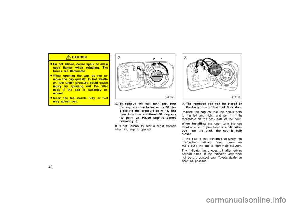
2. To remove the fuel tank cap, turnthe cap counterclockwise by 90 de-
grees (to the pressure point 1), and
then turn it a additional 30 degrees
(to point 2). Pause slightly before
removing it.
It is not unusual to hear a slight swoosh
when the cap is opened.
21p115
3. The removed cap can be stored on the back side of the fuel filler door.
Position the cap so that the hooks point
to the left and right, and set it in the
receptacle on the back side of the door.
When installing the cap, turn the cap
clockwise until you hear a click. When
you hear the click, the cap is fully
closed.
If the cap is not tightened securely, the
malfunction indicator lamp comes on.
Make sure the cap is tightened securely.
The indicator lamp goes off after driving
several times. If the indicator lamp does
not go off, contact your Toyota dealer as
soon as possible.
Page 162 of 336

162
YOUR RADIO ANTENNA
To remove an antenna on the roof, care-
fully turn it counterclockwise.
NOTICE
To prevent damage to the antenna,
make sure to remove it before driving
your Toyota through an automatic car
wash.
YOUR CASSETTE PLAYER
When you insert a cassette, the exposed
tape should be to the right.
NOTICE
Do not oil any part of the player and
do not insert anything other than cas-
sette tapes into the slot, or the tape
player may be damaged.
YOUR COMPACT DISC PLAYER
When you insert a disc, gently push it in
with the label side up.
The discs set in the player are played
continuously, starting with disc number 1.
The disc number of the disc currently be-
ing played, the track number and the time
from the beginning of the program appear
on the display.
Type 2 only:
When play of one disc ends, the first
track of the following disc starts. When
play of the final disc ends, play of the
first disc starts again.
The player will skip any empty disc num-
ber.
NOTICE
�Do not stack up two discs for in-
sertion, or it will cause damage the
compact disc player. Insert only one
compact disc into slot at a time.
� Never try to disassemble or oil any
part of the compact disc player. Do
not insert anything other than com-
pact discs into the slot.
The player is intended for use with 12 cm
(4.7 in.) discs only.
Page 192 of 336

192
Clock
28p009d
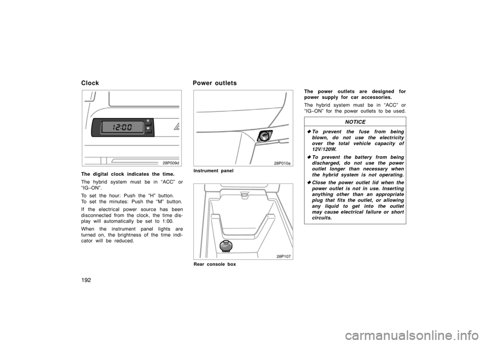
The digital clock indicates the time.
The hybrid system must be in “ACC” or
“IG−ON”.
To set the hour: Push the “H” button.
To set the minutes: Push the “M” button.
If the electrical power source has been
disconnected from the clock, the time dis-
play will automatically be set to 1:00.
When the instrument panel lights are
turned on, the brightness of the time indi-
cator will be reduced.
Power outlets
28p010a
Instrument panel
28p107
Rear console box
The power outlets are designed for
power supply for car accessories.
The hybrid system must be in “ACC” or
“IG −ON” for the power outlets to be used.
NOTICE
� To prevent the fuse from being
blown, do not use the electricity
over the total vehicle capacity of
12V/120W.
� To prevent the battery from being
discharged, do not use the power
outlet longer than necessary when
the hybrid system is not operating.
� Close the power outlet lid when the
power outlet is not in use. Inserting
anything other than an appropriate
plug that fits the outlet, or allowing
any liquid to get into the outlet
may cause electrical failure or short
circuits.