Page 120 of 5135

031H1±01
± SERVICE SPECIFICATIONSENGINE MECHANICAL
03±13
AVENSIS REPAIR MANUAL (RM1018E)
ENGINE MECHANICAL
SERVICE DATA
1ZZ±FE/3ZZ±FE:
Ignition timing w/ Terminal TC and CG of DLC3 connected
W/ Terminal TC and CG of DLC3 disconnected8 to 12�BTDC
10 to 18�BTDC (1ZZ±FE)
3.5 to 11.5�BTDC (3ZZ±FE)
Idle speed600 to 700 rpm
Compression
Compression pressure
Minimum pressure
Difference between each cylinder
1,300 kPa (13.3 kgf�cm2, 189 psi)
1,000 kPa (10.2 kgf�cm2, 145 psi)
100 kPa (1.0 kgf�cm2, 14 psi)
Cylinder head set bolt Length Standard
Maximum146.8 to 148.2 mm (5.780 to 5.835 in.)
148.5 mm (5.846 in.)
Valve clearance (Cold)
No. 1 Cylinder TDC/Compression Intake
Exhaust
No. 4 Cylinder TDC/Compression Intake
Exhaust
0.15 to 0.25 mm (0.0059 to 0.0098 in.)
0.25 to 0.35 mm (0.0098 to 0.0138 in.)
0.15 to 0.25 mm (0.0059 to 0.0098 in.)
0.25 to 0.35 mm (0.0098 to 0.0138 in.)
1AZ±FE:
Battery specific gravity at 20�C (68�F)1.25 to 1.29
Ignition timing w/ Terminals TC and CG of DLC3 connected
w/ Terminals TC and CG of DLC3 disconnected8 to 12� BTDC
5 to 15� BTDC
Idle speed650 to 750 rpm
Compression
Compression pressure
Minimum pressure
Difference between each cylinder
1,300 kPa (13.3 kgf/cm2, 189 psi)
1,000 kPa (10.2 kgf/cm2, 145 psi)
100 kPa (1.0 kgf/cm2, 14 psi)
Cylinder head set bolt
Bolt length Standard
Maximum
161.3 to 162.3 mm (6.350 to 6.390 in.)
164.2 mm (6.465 in.)
Valve clearance
Intake (Cold)
Exhaust
0.19 to 0.29 mm (0.0075 to 0.0114 in.)
0.30 to 0.40 mm (0.0118 to 0.0157 in.)
1AZ±FSE:
Battery specific gravity at 20�C (68�F)1.25 to 1.29
Ignition timing w/ Terminals TC and CG of DLC3 connected
w/ Terminals TC and CG of DLC3 disconnected8 to 12� BTDC
5 to 23� BTDC
Idle speed625 to 725 rpm
Compression
Compression pressure
Minimum pressure
Difference between each cylinder
1,300 kPa (13.3 kgf/cm2, 189 psi)
1,000 kPa (10.2 kgf/cm2, 145 psi)
100 kPa (1.0 kgf/cm2, 14 psi)
Cylinder head set bolt
Bolt length Standard
Maximum
161.3 to 162.3 mm (6.350 to 6.390 in.)
164.2 mm (6.465 in.)
Valve clearance
Intake (Cold)
Exhaust
0.19 to 0.29 mm (0.0075 to 0.0114 in.)
0.30 to 0.40 mm (0.0118 to 0.0157 in.)
Page 2114 of 5135
A30857
A62814
4 2531
A62816
2
5 3
110 8 4 796
A62827
Lot No.
A62820
Overall Length
± ENGINE MECHANICALCYLINDER HEAD GASKET (1ZZ±FE/3ZZ±FE)
14±87
AVENSIS REPAIR MANUAL (RM1018E)
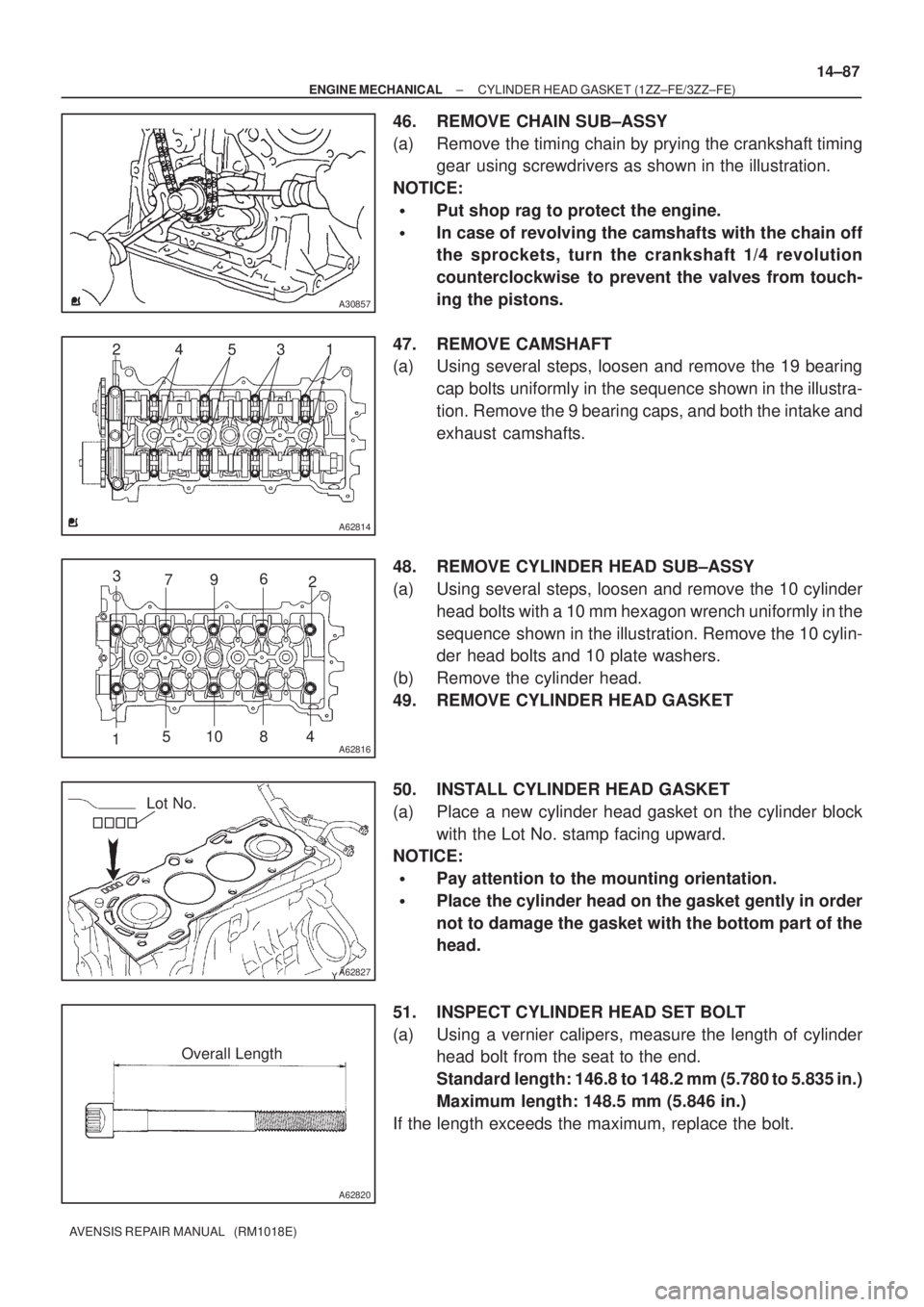
46. REMOVE CHAIN SUB±ASSY
(a) Remove the timing chain by prying the crankshaft timing
gear using screwdrivers as shown in the illustration.
NOTICE:
�Put shop rag to protect the engine.
�In case of revolving the camshafts with the chain off
the sprockets, turn the crankshaft 1/4 revolution
counterclockwise to prevent the valves from touch-
ing the pistons.
47. REMOVE CAMSHAFT
(a) Using several steps, loosen and remove the 19 bearing
cap bolts uniformly in the sequence shown in the illustra-
tion. Remove the 9 bearing caps, and both the intake and
exhaust camshafts.
48. REMOVE CYLINDER HEAD SUB±ASSY
(a) Using several steps, loosen and remove the 10 cylinder
head bolts with a 10 mm hexagon wrench uniformly in the
sequence shown in the illustration. Remove the 10 cylin-
der head bolts and 10 plate washers.
(b) Remove the cylinder head.
49. REMOVE CYLINDER HEAD GASKET
50. INSTALL CYLINDER HEAD GASKET
(a) Place a new cylinder head gasket on the cylinder block
with the Lot No. stamp facing upward.
NOTICE:
�Pay attention to the mounting orientation.
�Place the cylinder head on the gasket gently in order
not to damage the gasket with the bottom part of the
head.
51. INSPECT CYLINDER HEAD SET BOLT
(a) Using a vernier calipers, measure the length of cylinder
head bolt from the seat to the end.
Standard length: 146.8 to 148.2 mm (5.780 to 5.835 in.)
Maximum length: 148.5 mm (5.846 in.)
If the length exceeds the maximum, replace the bolt.
Page 5057 of 5135
A62816
2
5 3
110 8 4 796
A96569
Lot No.
A62820
Under head Length
A62816
84 2 59
7 3 1 6 10
A62823
Paint Mark
90�
Front
14–38– ENGINE MECHANICALCYLINDER HEAD GASKET (1ZZ–FE/3ZZ–FE)(From
February, 2004)
AVENSIS REPAIR MANUAL SUPPLEMENT
(RM1098E)
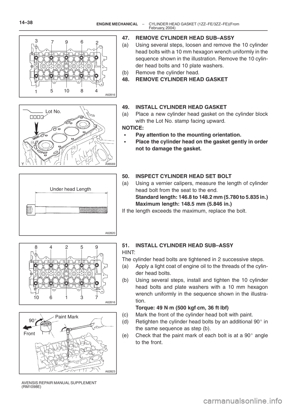
47. REMOVE CYLINDER HEAD SUB–ASSY
(a) Using several steps, loosen and remove the 10 cylinder
head bolts with a 10 mm hexagon wrench uniformly in the
sequence shown in the illustration. Remove the 10 cylin-
der head bolts and 10 plate washers.
(b) Remove the cylinder head.
48. REMOVE CYLINDER HEAD GASKET
49. INSTALL CYLINDER HEAD GASKET
(a) Place a new cylinder head gasket on the cylinder block
with the Lot No. stamp facing upward.
NOTICE:
�Pay attention to the mounting orientation.
�Place the cylinder head on the gasket gently in order
not to damage the gasket.
50. INSPECT CYLINDER HEAD SET BOLT
(a) Using a vernier calipers, measure the length of cylinder
head bolt from the seat to the end.
Standard length: 146.8 to 148.2 mm (5.780 to 5.835 in.)
Maximum length: 148.5 mm (5.846 in.)
If the length exceeds the maximum, replace the bolt.
51. INSTALL CYLINDER HEAD SUB–ASSY
HINT:
The cylinder head bolts are tightened in 2 successive steps.
(a) Apply a light coat of engine oil to the threads of the cylin-
der head bolts.
(b) Using several steps, install and tighten the 10 cylinder
head bolts and plate washers with a 10 mm hexagon
wrench uniformly in the sequence shown in the illustra-
tion.
Torque: 49 N⋅m (500 kgf⋅cm, 36 ft⋅lbf)
(c) Mark the front of the cylinder head bolt with paint.
(d) Retighten the cylinder head bolts by an additional 90� in
the same sequence as step (b).
(e) Check that the paint mark of each bolt is at a 90� angle
to the front.