Page 1310 of 5135

Buckle SWAirbag Sensor Assy Center
14
A28
3
A28 05±1250
± DIAGNOSTICSSUPPLEMENTAL RESTRAINT SYSTEM
AVENSIS REPAIR MANUAL (RM1018E)
DTC")
H42513
RBE+
RBE± G±Y
W±B 3
1 B9
Buckle SW (Driver's Seat)
Buckle SWAirbag Sensor Assy Center
14
A28
3
A28 05±1250
± DIAGNOSTICSSUPPLEMENTAL RESTRAINT SYSTEM
AVENSIS REPAIR MANUAL (RM1018E)
DTC B0121/26 SEAT BELT BUCKLE SWITCH (RH)
MALFUNCTION
DTC B0122/26 SEAT BELT BUCKLE SWITCH (RH)
MALFUNCTION
CIRCUIT DESCRIPTION
The seat belt buckle switch RH circuit consists of the airbag sensor assy center and the front seat inner belt
assy RH (seat belt buckle switch RH).
DTC B0121/26 or B0122/26 is recorded when a malfunction is detected in the seat belt buckle switch RH
circuit.
DTC No.DTC Detecting ConditionTrouble Area
B0121/B0122/
26
�Short circuit in seat belt buckle switch RH wire harness (to
ground)
�Short circuit in seat belt buckle switch RH wire harness (to
B+)
�Seat belt buckle switch RH malfunction
�Airbag sensor assy center
�Front seat inner belt assy RH (Seat belt buckle switch RH)
�Airbag sensor assy center
�Floor wire No.2
HINT:
DTC B0121/26 or B0122/26 is indicated only for the RHD vehicle.
WIRING DIAGRAM
056M5±03
Page 1311 of 5135

������������H42229
Airbag
Sensor
Assy
Center
Front Seat Inner
Belt Assy RHFloor Wire No.2
RBE+
A
B
C D
������������H42229
Airbag
Sensor
Assy
Center
Front Seat Inner
Belt Assy RHFloor Wire No.2
RBE+
A
B
C D
± DIAGNOSTICSSUPPLEMENTAL RESTRAINT SYSTEM
05±1251
AVENSIS REPAIR MANUAL (RM1018E)
INSPECTION PROCEDURE
1 CHECK FLOOR WIRE NO.2(TO B+)
(a) Turn the ignition switch to the LOCK position.
(b) Disconnect the negative (±) terminal cable from the bat-
tery, and wait for at least 90 seconds.
(c) Disconnect the connectors from the airbag sensor assy
center and the front seat inner belt assy RH.
(d) Connect the negative (±) terminal cable to the battery,
and turn the ignition switch to the ON position.
(e) Measure the voltage between the body ground and RBE+
of the connector ºBº.
OK:
Voltage: Below 1 V
NG REPAIR OR REPLACE FLOOR WIRE NO.2
OK
2 CHECK FLOOR WIRE NO.2(TO GROUND)
(a) Turn the ignition switch to the LOCK position.
(b) Disconnect the negative (±) terminal cable from the bat-
tery, and wait for at least 90 seconds.
(c) Measure the resistance between the body ground and
RBE+ of the connector ºBº.
OK:
Resistance: 1 M� or Higher
NG REPAIR OR REPLACE FLOOR WIRE NO.2
OK
Page 1312 of 5135
H42509
Airbag
Sensor
Assy
Center Front Seat Inner
Belt Assy RHFloor Wire No.2
RBE±
RBE+
A
B
H42509
Airbag
Sensor
Assy
Center Front Seat Inner
Belt Assy RHFloor Wire No.2
RBE±
RBE+
A
B
05±1252
± DIAGNOSTICSSUPPLEMENTAL RESTRAINT SYSTEM
AVENSIS REPAIR MANUAL (RM1018E)
3 CHECK FRONT SEAT INNER BELT ASSY RH
(a) Connect the connector to the front seat inner belt assy
RH.
(b) Unlock the seat belt at the front seat RH.
(c) Measure the resistance between RBE+ and RBE± of the
connector ºBº.
OK:
Resistance: 1.0 k� to 1.6 k�
NG REPLACE FRONT SEAT INNER BELT ASSY RH
OK
4 CHECK FRONT SEAT INNER BELT ASSY RH
(a) Lock the seat belt at the front seat RH.
(b) Measure the resistance between the RBE+ and RBE± of
the connector ºBº.
OK:
Resistance: 100 � to 500 �
NG REPLACE FRONT SEAT INNER BELT ASSY RH
OK
Page 1313 of 5135
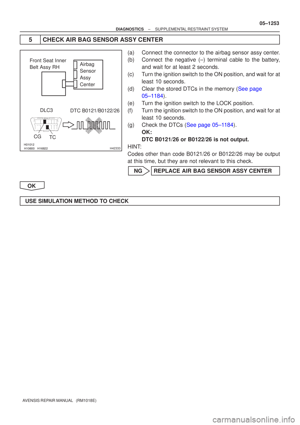
������������������H42333
Airbag
Sensor
Assy
Center
Front Seat Inner
Belt Assy RH
DLC3
CG TC DTC B0121/B0122/26
±
DIAGNOSTICS SUPPLEMENTAL RESTRAINT SYSTEM
05±1253
AVENSIS REPAIR MANUAL (RM1018E)
5CHECK AIR BAG SENSOR ASSY CENTER
(a)Connect the connector to the airbag sensor assy center.
(b)Connect the negative (±) terminal cable to the battery,
and wait for at least 2 seconds.
(c)Turn the ignition switch to the ON position, and wait for at least 10 seconds.
(d)Clear the stored DTCs in the memory (See page 05±1184).
(e) Turn the ignition switch to the LOCK position.
(f) Turn the ignition switch to the ON position, and wait for at least 10 seconds.
(g)Check the DTCs (See page 05±1184).
OK:
DTC B0121/26 or B0122/26 is not output.
HINT:
Codes other than code B0121/26 or B0122/26 may be output
at this time, but they are not relevant to this check.
NG REPLACE AIR BAG SENSOR ASSY CENTER
OK
USE SIMULATION METHOD TO CHECK
Page 1314 of 5135

DTC B0118/46 SHORT IN")
\b�����\b�����H42853
Side Squib LHAirbag
Sensor
Assy
Center
SFL±
SFL+Floor Wire
A
B
C
D
±
DIAGNOSTICS SUPPLEMENTAL RESTRAINT SYSTEM
05±1247
AVENSIS REPAIR MANUAL (RM1018E)
DTC B0118/46 SHORT IN SIDE SQUIB (LH) CIRCUIT (TO
B+)
CIRCUIT DESCRIPTION
The side squib LH circuit consists of the airbag sensor assy center and the\
separate type front seat back
assy (side squib LH).
This circuit actuates the SRS to deploy when the SRS deployment conditio\
ns are fulfilled.
DTC B0118/46 is recorded when a short to B+ is detected in the side squib LH ci\
rcuit.
DTC No.DTC Detecting ConditionTrouble Area
B0118/46
�Short circuit in side squib LH wire harness (to B+)
� Side squib LH malfunction
� Airbag sensor assy center malfunction�Separate type front seat back assy (Side squib LH)
� Airbag sensor assy center
� Floor wire
WIRING DIAGRAM
See page 05±1238.
INSPECTION PROCEDURE
1 CHECK FLOOR WIRE(SIDE SQUIB LH CIRCUIT)
(a) Turn the ignition switch to the LOCK position.
(b) Disconnect the negative (±) terminal cable from the bat-
tery, and wait for at least 90 seconds.
(c) Disconnect the connectors from the airbag sensor assy center and the separate type front seat back assy (side
squib LH).
(d) Connect the negative (±) terminal cable to the battery,
and turn the ignition switch to the ON position.
(e) Measure the voltage between the body ground and SFL+ of the connector ºCº.
OK:
Voltage: Below 1 V
NG REPAIR OR REPLACE FLOOR WIRE
OK
054LY±06
Page 1315 of 5135

\b�����
\b����� \b�����\b�����H42856
Side Squib LH
CGTC DTC B0118/46
DLC3 Airbag
Sensor
Assy
Center
SFL±
SFL+
Floor Wire
Service Wire
C
D
05±1248
±
DIAGNOSTICS SUPPLEMENTAL RESTRAINT SYSTEM
AVENSIS REPAIR MANUAL (RM1018E)
2 CHECK AIR BAG SENSOR ASSY CENTER
(a) Turn the ignition switch to the LOCK position.
(b) Disconnect the negative (±) terminal cable from the bat- tery, and wait for at least 90 seconds.
(c) Connect the connector to the airbag sensor assy center.
(d) Using a service wire, connect SFL+ and SFL± of the con- nector ºCº.
NOTICE:
Do not forcibly insert a service wire into the terminal of the
connector when connecting.
(e) Connect the negative (±) terminal cable to the battery, and wait for at least 2 seconds.
(f) Turn the ignition switch to the ON position, and wait for at least 10 seconds.
(g)Clear the stored DTCs in the memory (See page 05±1184).
(h) Turn the ignition switch to the LOCK position.
(i) Turn the ignition switch to the ON position, and wait for at
least 10 seconds.
(j)Check the DTCs (See page 05±1184). OK:
DTC B0118/46 is not output.
HINT:
Codes other than code B0118/46 may be output at this time, but
they are not related to this check.
NG REPLACE AIR BAG SENSOR ASSY CENTER
OK
Page 1316 of 5135

3 CHECK SEPARATE")
������
������ ������H40994
Side Squib LHDTC B0118/46
DLC3
TC
CG Airbag
Sensor
Assy
Center
C
D
±
DIAGNOSTICS SUPPLEMENTAL RESTRAINT SYSTEM
05±1249
AVENSIS REPAIR MANUAL (RM1018E)
3 CHECK SEPARATE TYPE FRONT SEAT BACK ASSY(SIDE SQUIB LH)
(a) Turn the ignition switch to the LOCK position.
(b) Disconnect the negative (±) terminal cable from the bat-
tery, and wait for at least 90 seconds.
(c) Connect the connector to the separate type front seat back assy (side squib LH).
(d) Connect the negative (±) terminal cable to the battery, and wait for at least 2 seconds.
(e) Turn the ignition switch to the ON position, and wait for at least 10 seconds.
(f)Clear the stored DTCs in the memory (See page 05±1184).
(g) Turn the ignition switch to the LOCK position.
(h) Turn the ignition switch to the ON position, and wait for at least 10 seconds.
(i)Check the DTCs (See page 05±1184). OK:
DTC B0118/46 is not output.
HINT:
Codes other than code B0118/46 may be output at this time, but
they are not related to this check.
NG REPLACE SEPARATE TYPE FRONT SEAT BACK ASSY
OK
4 USE SIMULATION METHOD TO CHECK
NG Go to step 1
OK
REPLACE ALL SRS COMPONENTS INCLUDING WIRE HARNESS
Page 1317 of 5135

DTC B0117/45 SHORT")
\b�����\b�����H42853
Airbag
Sensor
Assy
Center
SFL±
SFL+
Side Squib LH
Floor Wire
A
B
C
D
05±1244
±
DIAGNOSTICS SUPPLEMENTAL RESTRAINT SYSTEM
AVENSIS REPAIR MANUAL (RM1018E)
DTC B0117/45 SHORT IN SIDE SQUIB (LH) CIRCUIT (TO GROUND)
CIRCUIT DESCRIPTION
The side squib LH circuit consists of the airbag sensor assy center and the\
separate type front seat back
assy (side squib LH).
This circuit actuates the SRS to deploy when the SRS deployment conditio\
ns are fulfilled.
DTC B0117/45 is recorded when a short to ground is detected in the side squib L\
H circuit.
DTC No.DTC Detecting ConditionTrouble Area
B0117/45
�Short circuit in side squib LH wire harness (to ground)
� Side squib LH malfunction
� Airbag sensor assy center malfunction�Separate type front seat back assy (Side squib LH)
� Airbag sensor assy center
� Floor wire
WIRING DIAGRAM
See page 05±1238.
INSPECTION PROCEDURE
1 CHECK FLOOR WIRE(SIDE SQUIB LH CIRCUIT)
(a) Turn the ignition switch to the LOCK position.
(b) Disconnect the negative (±) terminal cable from the bat-
tery, and wait for at least 90 seconds.
(c) Disconnect the connectors from the airbag sensor assy center and the separate type front seat back assy (side
squib LH).
(d) Measure the resistance between the body ground and
SFL+ of the connector ºCº.
OK:
Resistance: 1 M � or Higher
NG REPAIR OR REPLACE FLOOR WIRE
OK
054LX±06