Page 4772 of 5135

40188−01
C91925
D30865
AT0103
C91927
− AUTOMATIC TRANSMISSION / TRANSTRANSMISSION VALVE BODY ASSY (U151E)
40−19
AVENSIS Supplement (RM1045E)
TRANSMISSION VALVE BODY ASSY (U151E)
REPLACEMENT
1. REMOVE ENGINE UNDER COVER LH
2. DRAIN AUTOMATIC TRANSAXLE FLUID
(a) Remove the drain plug and gasket, and drain ATF.
(b) Install a new gasket and the drain plug.
Torque: 47 N�m (479 kgf�cm, 35 ft�lbf)
3. REMOVE AUTOMATIC TRANSAXLE OIL PAN
SUB−ASSY
(a) Remove the 18 bolts, oil pan and gasket.
NOTICE:
Some fluid will remain in the oil pan. Remove all of the oil
pan bolts, and carefully remove the oil pan assembly.
(b) Remove the 2 magnets from the oil pan.
(c) Examine the particles in the oil pan.
(1) Collect any steel chips with the removed magnets.
Look at the chips and particles in the pan and on the
magnets carefully to see the type of wear which
might be found in the transaxle.
Steel (magnetic): bearing, gear and plate wear
Brass (non−magnetic): bearing wear
4. DISCONNECT TRANSMISSION WIRE
(a) Disconnect the 7 shift solenoid valve connectors.
(b) Remove the bolt and lock plate, and disconnect the ATF
temperature sensor.
Page 4777 of 5135

40187−01
C91925
D30865
AT0103
C91927
40−16
− AUTOMATIC TRANSMISSION / TRANSTRANSMISSION WIRE (U151E)
AVENSIS Supplement (RM1045E)
TRANSMISSION WIRE (U151E)
REPLACEMENT
1. REMOVE ENGINE UNDER COVER LH
2. DRAIN AUTOMATIC TRANSAXLE FLUID
(a) Remove the drain plug and gasket, and drain ATF.
(b) Install a new gasket and the drain plug.
Torque: 47 N�m (479 kgf�cm, 35 ft�lbf)
3. REMOVE AUTOMATIC TRANSAXLE OIL PAN
SUB−ASSY
(a) Remove the 18 bolts, oil pan and gasket.
NOTICE:
Some fluid will remain in the oil pan. Remove all of the oil
pan bolts, and carefully remove the oil pan assembly.
(b) Remove the 2 magnets from the oil pan.
(c) Examine the particles in the oil pan.
(1) Collect any steel chips with the removed magnets.
Look at the chips and particles in the pan and on the
magnets carefully to see the type of wear which
might be found in the transaxle.
Steel (magnetic): bearing, gear and plate wear
Brass (non−magnetic): bearing wear
4. DISCONNECT TRANSMISSION WIRE
(a) Disconnect the 7 shift solenoid valve connectors.
(b) Remove the bolt and lock plate, and disconnect the ATF
temperature sensor.
Page 4849 of 5135
C83143
Union
O−ring
C83144
Elbow
O−ring
D03900D30672
Speed Sensor
D26716
D09176
− AUTOMATIC TRANSMISSION / TRANSAUTOMATIC TRANSAXLE ASSY (U151E/U151F)
40−19
U151E, U151F A/T REPAIR MANUAL (RM1021U)
4. REMOVE OIL COOLER TUBE UNION (INLET OIL
COOLER UNION)
(a) Remove the union.
(b) Remove the O−ring from the union.
5. REMOVE OIL COOLER TUBE UNION (OUTLET OIL
COOLER UNION)
(a) Remove the elbow.
(b) Remove the O−ring from the elbow.
6. REMOVE SPEED SENSOR
(a) Remove the 2 bolts and the 2 speed sensors from the
transaxle assy.
7. REMOVE TRANSAXLE CASE NO.1PLUG
(a) Remove the 4 transaxle case No. 1 plugs from the trans-
axle case.
(b) Remove the 4 O−rings from the 4 transaxle case No.1
plugs.
8. FIX AUTOMATIC TRANSAXLE ASSY
(a) Fix the transaxle assy.
Page 4861 of 5135
D26388
Rear Clutch
Oil Seal
Ring Outer
D26389
D26472
SST
D26390
D26391
Brake Apply Tube
Clutch Apply Tube
− AUTOMATIC TRANSMISSION / TRANSAUTOMATIC TRANSAXLE ASSY (U151E/U151F)
40−31
U151E, U151F A/T REPAIR MANUAL (RM1021U)
46. REMOVE TRANSAXLE CASE NO.1PLUG
(a) Remove the 4 transaxle case No.1 plugs from the trans-
axle rear cover.
(b) Remove the 4 O−rings from the 4 transaxle case No.1
plugs.
47. REMOVE REAR CLUTCH OIL SEAL RING OUTER
(a) Remove the 3 rear clutch oil seal rings from the transaxle
rear cover.
48. REMOVE NEEDLE ROLLER BEARING
(a) Using SST, remove the needle−roller bearing from the
transaxle rear cover.
SST 09387−00041 (09387−01021, 09387−01030,
09387−01040)
49. REMOVE GOVERNOR APPLY GASKET NO.1
(a) Using a screwdriver, remove the 3 apply gaskets.
50. REMOVE BRAKE APPLY TUBE
(a) Remove the bolt, clamp and brake apply tube.
(b) Remove the clutch apply tube.
(c) Remove the brake apply tube from the clamp.
Page 4870 of 5135
D03605
SSTHold
Turn
D03914
Underdrive
Clutch Drum
Oil Seal Ring
D26383
D03606
SST
Hold
Turn
D03915
Underdrive
Output
Shaft Oil
Seal Ring
40−40
− AUTOMATIC TRANSMISSION / TRANSAUTOMATIC TRANSAXLE ASSY (U151E/U151F)
U151E, U151F A/T REPAIR MANUAL (RM1021U)
76. REMOVE NEEDLE ROLLER BEARING
(a) Using SST, remove the needle−roller bearing from the
transaxle case.
SST 09387−00041 (09387−01010, 09387−01030,
09387−01040)
77. REMOVE UNDERDRIVE CLUTCH DRUM OIL SEAL
RING
(a) Remove the 2 oil seal rings from the transaxle case.
78. REMOVE TRANSAXLE CASE NO.1PLUG
(a) Remove the 2 transaxle case No. 1 plugs.
(b) Remove the 2 O−rings from the 2 transaxle case No. 1
plugs.
79. REMOVE UNDERDRIVE CYLINDRICAL ROLLER
BEARING
(a) Using SST, remove the underdrive cylindrical roller bear-
ing from the transaxle case.
SST 09514−35011
80. REMOVE UNDERDRIVE OUTPUT SHAFT OIL SEAL
RING
(a) Remove the oil seal ring from the transaxle housing.
Page 4874 of 5135

D26400
Transaxle Apply
Tube Clamp
Differential Gear Lube Apply Tube
D26383
Underdrive
Output Shaft
Oil Seal Ring
D03915
AT F
D03807
SST
D03914
Underdrive
Clutch Drum
Oil Seal Ring
AT F 40−44
− AUTOMATIC TRANSMISSION / TRANSAUTOMATIC TRANSAXLE ASSY (U151E/U151F)
U151E, U151F A/T REPAIR MANUAL (RM1021U)
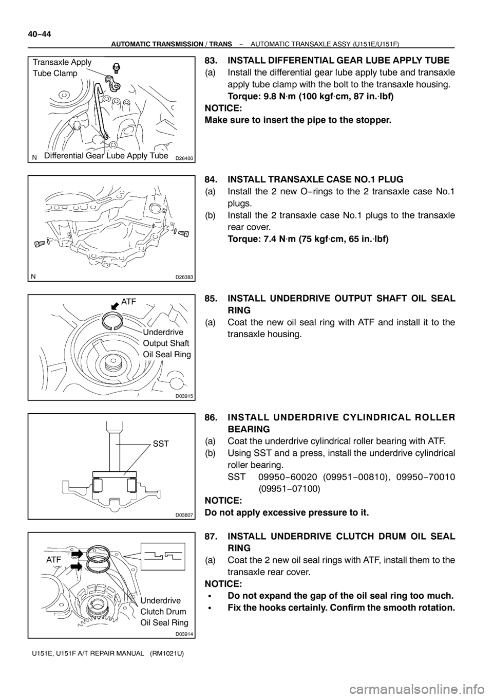
83. INSTALL DIFFERENTIAL GEAR LUBE APPLY TUBE
(a) Install the differential gear lube apply tube and transaxle
apply tube clamp with the bolt to the transaxle housing.
Torque: 9.8 N�m(100 kgf�cm, 87 in.�lbf)
NOTICE:
Make sure to insert the pipe to the stopper.
84. INSTALL TRANSAXLE CASE NO.1PLUG
(a) Install the 2 new O−rings to the 2 transaxle case No.1
plugs.
(b) Install the 2 transaxle case No.1 plugs to the transaxle
rear cover.
Torque: 7.4 N�m (75 kgf�cm, 65 in.�lbf)
85. INSTALL UNDERDRIVE OUTPUT SHAFT OIL SEAL
RING
(a) Coat the new oil seal ring with ATF and install it to the
transaxle housing.
86. INSTALL UNDERDRIVE CYLINDRICAL ROLLER
BEARING
(a) Coat the underdrive cylindrical roller bearing with ATF.
(b) Using SST and a press, install the underdrive cylindrical
roller bearing.
SST 09950−60020 (09951−00810), 09950−70010
(09951−07100)
NOTICE:
Do not apply excessive pressure to it.
87. INSTALL UNDERDRIVE CLUTCH DRUM OIL SEAL
RING
(a) Coat the 2 new oil seal rings with ATF, install them to the
transaxle rear cover.
NOTICE:
SDo not expand the gap of the oil seal ring too much.
SFix the hooks certainly. Confirm the smooth rotation.
Page 4887 of 5135

D26766
SST
D26389
Rear Clutch
Oil Seal
Ring Outer
D26388
D26454
FIPG
− AUTOMATIC TRANSMISSION / TRANSAUTOMATIC TRANSAXLE ASSY (U151E/U151F)
40−57
U151E, U151F A/T REPAIR MANUAL (RM1021U)
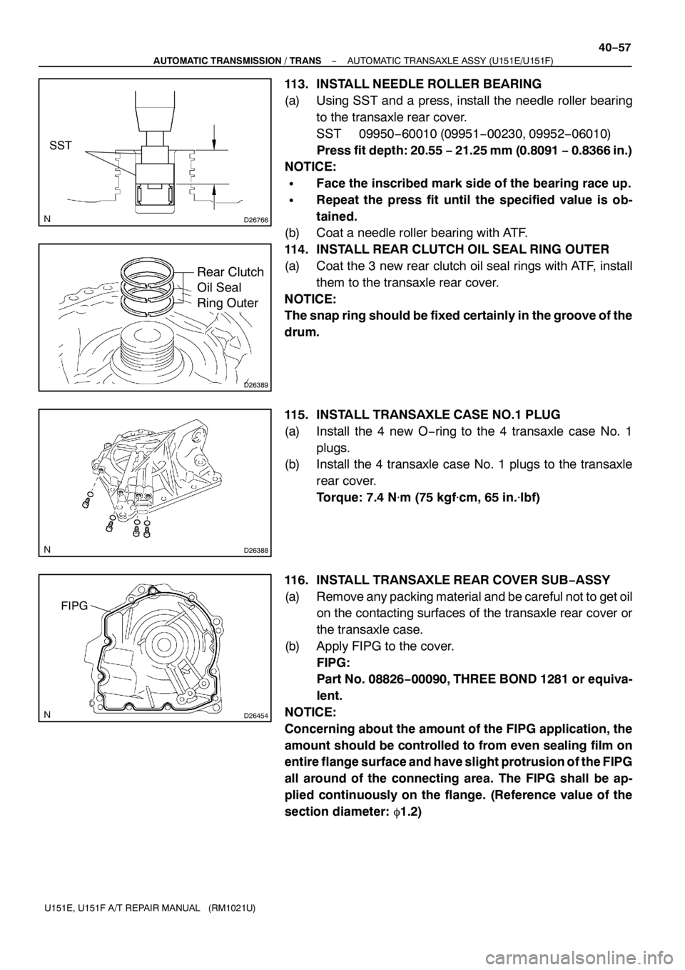
113. INSTALL NEEDLE ROLLER BEARING
(a) Using SST and a press, install the needle roller bearing
to the transaxle rear cover.
SST 09950−60010 (09951−00230, 09952−06010)
Press fit depth: 20.55−21.25 mm (0.8091−0.8366 in.)
NOTICE:
SFace the inscribed mark side of the bearing race up.
SRepeat the press fit until the specified value is ob-
tained.
(b) Coat a needle roller bearing with ATF.
114. INSTALL REAR CLUTCH OIL SEAL RING OUTER
(a) Coat the 3 new rear clutch oil seal rings with ATF, install
them to the transaxle rear cover.
NOTICE:
The snap ring should be fixed certainly in the groove of the
drum.
115. INSTALL TRANSAXLE CASE NO.1PLUG
(a) Install the 4 new O−ring to the 4 transaxle case No. 1
plugs.
(b) Install the 4 transaxle case No. 1 plugs to the transaxle
rear cover.
Torque: 7.4 N�m (75 kgf�cm, 65 in.�lbf)
116. INSTALL TRANSAXLE REAR COVER SUB−ASSY
(a) Remove any packing material and be careful not to get oil
on the contacting surfaces of the transaxle rear cover or
the transaxle case.
(b) Apply FIPG to the cover.
FIPG:
Part No. 08826−00090, THREE BOND1281or equiva-
lent.
NOTICE:
Concerning about the amount of the FIPG application, the
amount should be controlled to from even sealing film on
entire flange surface and have slight protrusion of the FIPG
all around of the connecting area. The FIPG shall be ap-
plied continuously on the flange. (Reference value of the
section diameter:�1.2)
Page 4901 of 5135

C91931
Valve Body Oil
Strainer Assy.
C86316
Magnet
C91925
D26716
D03900D30672
Speed Sensor
− AUTOMATIC TRANSMISSION / TRANSAUTOMATIC TRANSAXLE ASSY (U151E/U151F)
40−71
U151E, U151F A/T REPAIR MANUAL (RM1021U)
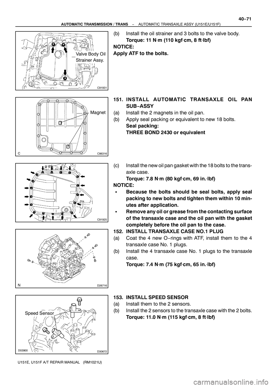
(b) Install the oil strainer and 3 bolts to the valve body.
Torque:11N�m(110 kgf�cm, 8 ft�lbf)
NOTICE:
Apply ATF to the bolts.
151. INSTALL AUTOMATIC TRANSAXLE OIL PAN
SUB−ASSY
(a) Install the 2 magnets in the oil pan.
(b) Apply seal packing or equivalent to new 18 bolts.
Seal packing:
THREE BOND 2430 or equivalent
(c) Install the new oil pan gasket with the 18 bolts to the trans-
axle case.
Torque: 7.8 N�m (80 kgf�cm, 69 in.�lbf)
NOTICE:
SBecause the bolts should be seal bolts, apply seal
packing to new bolts and tighten them within10 min-
utes after application.
SRemove any oil or grease from the contacting surface
of the transaxle case and the oil pan with the gasket
completely before the oil pan to the case.
152. INSTALL TRANSAXLE CASE NO.1PLUG
(a) Coat the 4 new O−rings with ATF, install them to the 4
transaxle case No. 1 plugs.
(b) Install the 4 transaxle case No. 1 plugs to the transaxle
case.
Torque: 7.4 N�m (75 kgf�cm, 65 in.�lbf)
153. INSTALL SPEED SENSOR
(a) Install them to the 2 sensors.
(b) Install the 2 sensors to the transaxle case with the 2 bolts.
Torque:11.0 N�m(115 kgf�cm, 8 ft�lbf)